Mid-chassis roof frame without high-cost tooling
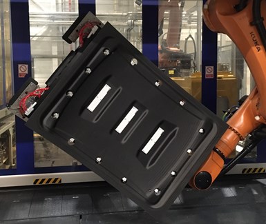
An extrusion-based 3D-printed core with AFP skins produced a mid-chassis roof frame that has comparable strength and stiffness to a hollow steel part — yet is 40% lighter with a 50% reduced cross section — and avoids the cost of injection molding tools in the previous MAI Skelett design. Photo Credit: BMW, TUM
In 2019, CW reported on a development project called MAI Skelett (see "Skeleton design enables more competitive autostructures”) led by BMW (Munich, Germany), which demonstrated an upper composite windshield frame (Fig. 1). It was designed to replace previous thermoset composite technology with unidirectional (UD) carbon fiber-reinforced thermoplastic (CFRTP) pultrusions that were thermoformed and injection overmolded in a two-step, 75-second process. Performance of the resulting structural roof member exceeded all previous version requirements, and in 2020, SGL Carbon (Wiesbaden, Germany) and Koller Kunststofftechnik GmbH (Lupburg, Germany) received a multi-year order from BMW for the production of CFRTP for serial use in front windshield and rear window frames. These frames can be seen in CW’s January 2022 article “BMW rolls out multi-material Carbon Cage with 2022 iX vehicle line” and after the 3:40 point in the video below.
In 2019, engineers from BMW began a collaboration with Technical University of Munich (TUM, Munich, Germany) to investigate how to use additive manufacturing (AM) to reduce injection molding costs in such parts. TUM had been conducting various research projects on how to combine more traditional composites manufacturing like layup via automated fiber placement (AFP) with 3D printing that uses continuous fiber reinforcement (see “Future composite manufacturing – AFP and Additive Manufacturing”). “Injection molding tools are quite expensive,” explains Franz Maidl, technology development engineer in BMW’s Lightweight Construction and Technology Center (Landshut, Germany). “Our goal was a fully comparable solution to the MAI Skelett technology but much less costly via additive manufacturing.”
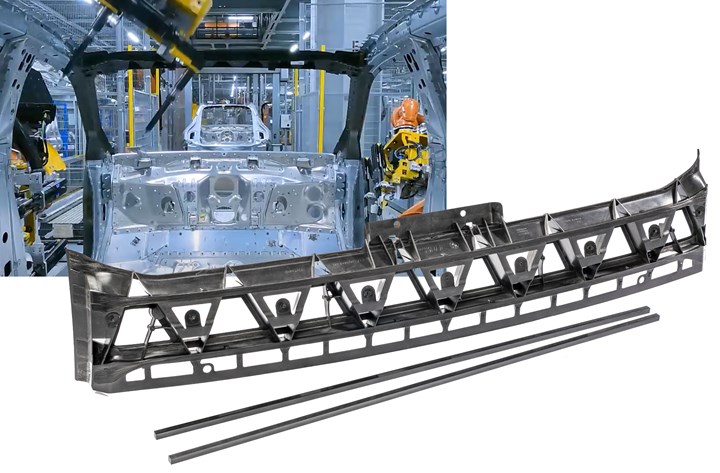
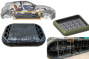
Fig. 1. MAI Skelett windshield frame
The MAI Skelett project demonstrated a thermoplastic composite frame made by injection overmolding carbon fiber pultrusions (at bottom). This was evolved and adopted for the BMW iX SUV (top left).
For this next evolution of the Skelett roof frame, two different demonstrators were built using two different AM methods combined with continuous CFRTP materials. The front roof frame demonstrated in the MAI Skelett project was revised using selective laser sintering (SLS) and injection or AFP while the part shown in this article combined extrusion-based 3D printing and AFP to produce a mid-roof frame, located at the B-pillar connection between the chassis side frames. Both frames are slightly curved and close out the chassis “box,” providing stiffness and resistance to torsion. However, the front roof frame also requires mating with the windshield and multiple attachments for interior parts.
SLS versus extrusion
Maidl’s team at BMW identified SLS and extrusion as the AM processes best-suited for the roof frames. SLS uses a laser to sinter powder materials into a solid as defined by a part’s 3D CAD model. For example, CRP Technology (Modena, Italy) makes composites parts using SLS with milled carbon fiber in several grades of its Windform materials. “For the SLS and CFRTP combination, we would print very complex structures in SLS to build up cavities into which we could inject or place thermoplastic CFRP material,” says Maidl. “We would first print the part and then place CFRP reinforcements followed by metal inserts.” The latter (seen extending from the right side of the part in the opening image at top) are used to connect the roof frames to the surrounding structure. The second process option was to use robot-based extrusion, where plastic pellets are melted and deposited by a 3D print head mounted on a robot. “This was much more interesting to us because it is cheaper than SLS,” notes Maidl.
“With extrusion, you can also use recycled materials,” notes Alexander Matschinski, research associate and expert for Additive Manufacturing at TUM. “We used an injection molding grade of material, which is 10 times cheaper than SLS materials.”
Maidl cites a cost of less than €5/kilogram, noting that “this is not possible with SLS. The problem with SLS is that you can reuse collected powder from previous prints, but it has already been heated once, so it has lost some of its properties and processability. Thus, you must have material comprised at least 50% by volume of new powder. You have to spend money to monitor this and ensure the ratio is correct. With extrusion, you can just crush previous material, put it in the melt hopper and use it again.” The extruder used for this project was supplied by Hans Weber Maschinenfabrik (Kronach, Germany).
“Extrusion also allows us to use material grades that are mass produced,” says Matschinski, “so, it is a very cost-effective process. The other aspect is the high material deposition. In large-scale processes, maximum material depositions of 2 to about 35 kilograms per hour are possible. Other processes are mostly limited to less than 1 kilogram per hour."
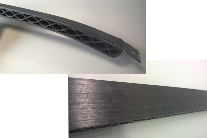
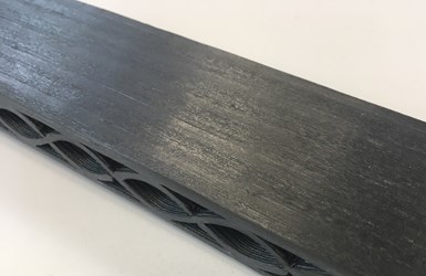
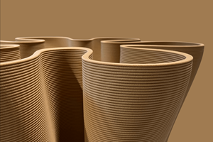
Fig. 2. 3D-printed core, AFP skin
A sinusoidal pattern enabled a continuous path for 3D printing an extruded CF/PA compound core, followed by AFP of UD CF/PA tapes on top and bottom to create a stiff, yet affordable structure. Photo Credit: BMW, TUM
For the project demonstrator, base geometry was printed using TUM’s AM Flexbot printer from CEAD (Delft, Netherlands) and a standard compound of polyamide (PA) reinforced with short carbon fiber (CF) supplied by AKRO-PLASTIC (Niederzissen, Germany). “We were then able to reinforce that locally with UD CF/PA tapes using AFP,” says Matschinski. Those tapes were supplied by SGL Carbon. Both were compatible for recycling, using the same type of fiber and matrix . “Our design was to build up a sandwich structure using a 3D-printed core which we used to place AFP skins on top and bottom,” explains Maidl. “Thus, we eliminated the tooling cost, which helps to create an economically interesting business case.”
3D-printed core
Why did this project choose the symmetrical sinusoidal wave pattern for the part’s core? “The best pattern to use depends on the printing process and also on the next process step as well as the overall mechanical performance you are seeking,” says Matschinski. “For our robot printer, the most effective pattern is to have continuous material deposition paths. So, this turns out to be an endless curved form from beginning to end, which is the sine wave you see (Fig 2). This then provides a platform onto which we can place the AFP tapes.
“Also, this part was basically a slightly curved beam, creating tension load on one side and compression load on the other,” he continues. “To transmit these loads from one side to the other you need plus and minus 45-degree fibers. The pattern we devised achieves this. The sine wave thus becomes the shear web. The radius of the curve was chosen to produce a smooth printing path with our robot.”
“We used 600 grams of material and printed the core in less than 30 minutes,” says Maidl. “This is very fast. We then moved the piece forward for placement of reinforcements using AFP, followed by the final step of integrating metal inserts and plates.” The metal inserts can be placed robotically or by hand using ultrasonic welding.
Process development and future applications
Matschinski says the all-robotic process is very repeatable, “but you have to bring the printed part in with defined geometry for the fiber placement. You can machine the part in certain areas to obtain the needed accuracy, for example, where inserts are needed or in areas that attach to other parts. This means combining the additive and subtractive processes, but the CEAD robot is already designed for this.”
He calculates the better business case is to print faster followed by machining to final dimensions, rather than print slowly and more accurately: “To compete with conventional injection molding of 100 kilograms/hour, it is better to print 10 kilograms/hour and only need to machine the surface slightly, than printing, for example, 1 kilogram/hour with high accuracy.”
“The answer also depends on where accuracy is needed or not,” adds Maidl. “The mid-roof frame has two points that connect to the car’s metallic frame. At these points, the tolerance is an issue, but in between these points it is not. For the front roof frame, using SLS with CFRTP achieved a higher accuracy, and let us overcome the issues with tolerance at the windshield and interior attachments,” he explains, noting that BMW is now working to apply the extrusion and AFP method to more complex parts.
“In the end, we produced parts that are 40% lighter versus a hollow steel part,” he says. “We also reduced the cross section of the mid-chassis frame by 50% with very comparable properties.” Matschinski notes this is just one example of what can be achieved by combining additive extrusion and AFP.
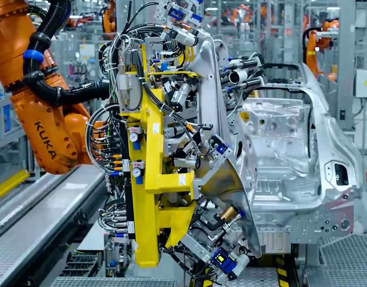
Fig. 3. Replacing metal in robot grippers
The combination of 3D printing and AFP has now been developed for lightweight, stiff grippers used by assembly robots to pick up large modules, like roofs and lift gates, with greater speed and precision. A conventional metal gripper is shown at top (yellow) and the new composite gripper at bottom (black rectangular part). This new approach reduces cost by 25%, weight by 20%, CO2 emissions by 60% and lead time by 50%. Photo Credit: BMW
The R&D project is now complete and the BMW team achieved a desired internal technology readiness level. “We had a lot of interest in the short fiber printed truss and have received approval to develop a structural part for a zero-emissions car project,” says Maidl.
“We also received interest to apply this technique for grippers,” he notes, “that are used by the production robots and handling equipment [Fig. 3]. We are offering a solution that is fast, cheap and lighter than the current metallic solutions in a gripper that picks up finished composite roofs and others that install such modules during assembly.” By combining AM and composites, these grippers can be made stiffer and/or lighter, but also with shorter lead times and cost for customized, one-off units, he notes. “For a range of applications, we see cost, weight and supply chain advantages for using additive manufacturing plus endless fiber and its potential to produce high-performance, affordable parts.”
Related Content
Plant tour: Teijin Carbon America Inc., Greenwood, S.C., U.S.
In 2018, Teijin broke ground on a facility that is reportedly the largest capacity carbon fiber line currently in existence. The line has been fully functional for nearly two years and has plenty of room for expansion.
Read MoreTU Munich develops cuboidal conformable tanks using carbon fiber composites for increased hydrogen storage
Flat tank enabling standard platform for BEV and FCEV uses thermoplastic and thermoset composites, overwrapped skeleton design in pursuit of 25% more H2 storage.
Read MoreSulapac introduces Sulapac Flow 1.7 to replace PLA, ABS and PP in FDM, FGF
Available as filament and granules for extrusion, new wood composite matches properties yet is compostable, eliminates microplastics and reduces carbon footprint.
Read MorePEEK vs. PEKK vs. PAEK and continuous compression molding
Suppliers of thermoplastics and carbon fiber chime in regarding PEEK vs. PEKK, and now PAEK, as well as in-situ consolidation — the supply chain for thermoplastic tape composites continues to evolve.
Read MoreRead Next
Modeling and characterization of crushable composite structures
How the predictive tool “CZone” is applied to simulate the axial crushing response of composites, providing valuable insights into their use for motorsport applications.
Read MorePlant tour: A&P, Cincinnati, OH
A&P has made a name for itself as a braider, but the depth and breadth of its technical aptitude comes into sharp focus with a peek behind usually closed doors.
Read More“Structured air” TPS safeguards composite structures
Powered by an 85% air/15% pure polyimide aerogel, Blueshift’s novel material system protects structures during transient thermal events from -200°C to beyond 2400°C for rockets, battery boxes and more.
Read More


