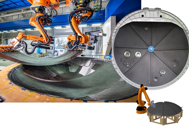
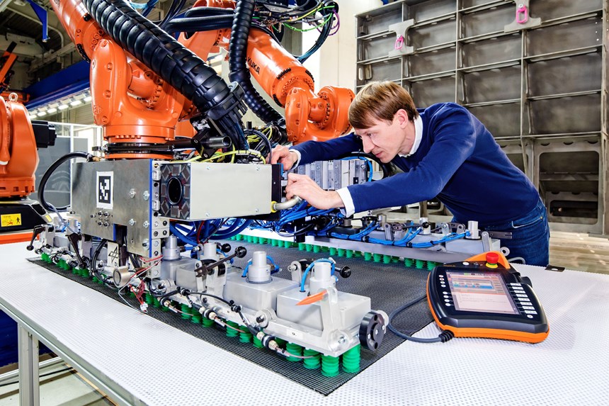
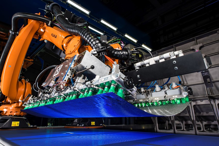
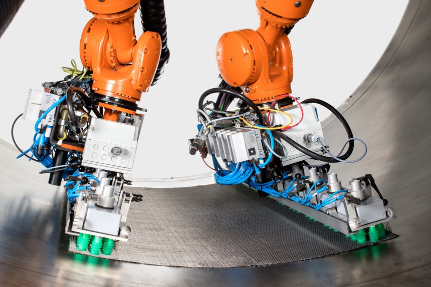
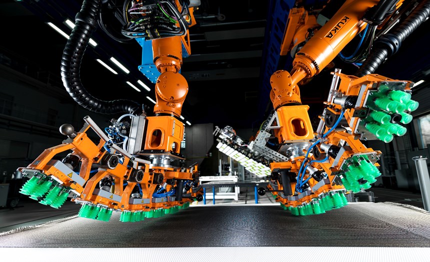
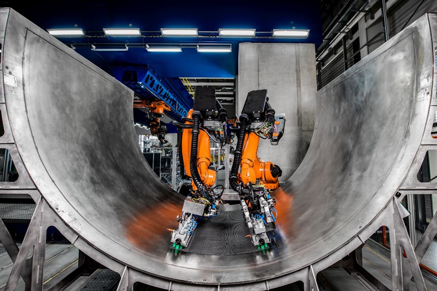
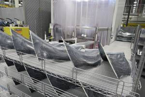
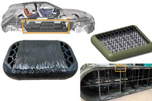
The DLR Center for Lightweight Production Technology (ZLP) has demonstrated an automated process for an A350 rear pressure bulkhead (RPB) using dry CF fabric (left) and resin infusion with Hexcel’s RTM6 epoxy. In a separate project, eight “petal” sections were press-molded from CF/PPS organosheet and ZLP used automated resistance welding to form an A320 RPB (right). Photo Credit: German Aerospace Center (DLR) Institute of Structures and Design
As OEMs and suppliers explore the materials and processes that will enable the next generation of aircraft, two different approaches are being demonstrated. The first is liquid molding of dry fiber preforms seen, for example, in Spirit AeroSystem’s (Prestwick, Scotland) high-rate resin transfer molding (RTM) line for Airbus A320 spoilers and also in the Airbus-led Wing of Tomorrow (WOT) program which uses automated placement of noncrimp fabrics (NCF) and liquid resin infusion, followed by out of autoclave (OOA) cure in an oven (see “High-rate, automated aerospace RTM line delivers next-gen spoilers” and “Update: Lower wing skin, Wing of Tomorrow” respectively.)
The second is thermoplastic composites (TPC) featured, for example, in the Clean Sky 2 Multifunctional Fuselage Demonstrator (MFFD), where stiffened skins are created using automated fiber placement — in-situ consolidated for the upper half and autoclave-consolidated for the lower half — followed by assembly via welding. These programs use automation to increase production rate and quality while reducing cost. But how do they compare?
The German Aerospace Center (DLR) Institute of Structures and Design operates the Center for Lightweight Production Technology (ZLP) in Augsburg. Among its many composites manufacturing projects, PROTEC NSR and Fast Lane RPB present a unique opportunity to compare, respectively, a liquid-molded thermoset rear pressure bulkhead (RPB) for the twin-aisle Airbus A350 with a thermoplastic RPB for the single-aisle Airbus A320. Both projects worked with the Tier 1 supplier of these structures, Premium Aerotec Group (PAG, Augsburg, Germany), and demonstrated automation while evaluating cycle time and cost.
Liquid-molded TS bulkhead
“We started many years ago with PAG in the AZIMUT project to analyze manual processes for composites manufacturing,” says Dr. Lars Larsen, head of assembly and joining technologies at ZLP Augsburg. “Our first automation solution was for layup, and then we worked to automate more operations.” The main goal for PROTEC NSR was to take these specialized solutions for RPB production and bring them into a single automated process, explains Dr. Marcin Malecha, project manager for PROTEC NSR at DLR.
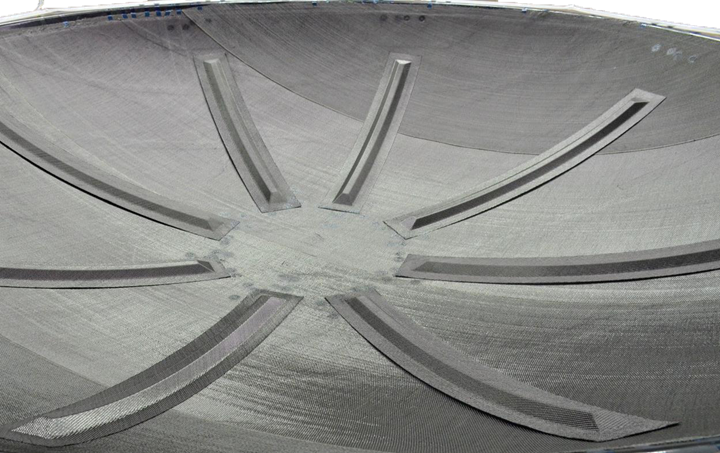
Dry carbon fiber preform for the liquid-molded PROTEC NSR rear pressure bulkhead.Photo Credit: German Aerospace Center (DLR) Institute of Structures and Design
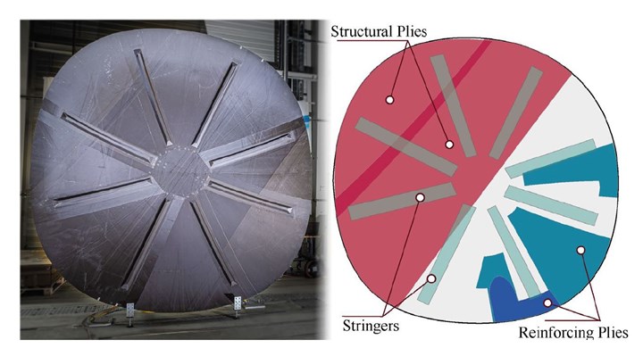
Preform and grippers. The process steps for creating the vacuum-bagged dry preform are shown in Fig. 1 below. This was infused with RTM6 epoxy resin using the Airbus-patented vacuum assisted process (VAP), which employs a semi-permeable membrane for reduced porosity. The preform layup comprised two sets of 16 plies up to 5 meters long using the full 1.27-meter width of the 5-harness satin carbon fiber fabric. Embedded between these two sets were 25 complex-shaped, reinforcing pieces sized up to 1.5 by 2.5 meters. Eight stringers were placed on top.
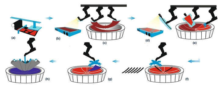
Fig. 1. Process steps for resin-infused RPB
PROTEC NSR process steps for creating the dry preform: (a) material cutting; (b) (d) material transport to the robotic cell; cut-piece recognition, picking up, draping and application of (c) reinforcing plies and (e) structural plies; (f) stringer integration; and vacuum bagging of (g) tool-side and (h) B-side/outer auxiliary materials. Photo Credit: German Aerospace Center (DLR) Institute of Structures and Design
“Developing tools and grippers that could achieve the necessary precision in draping and handling was one of the biggest challenges,” notes Larsen. This was partly due to the complex mix of plies that required three different draping mechanisms:
- Application of full-width material directly from the roll that must adapt to the shape of the mold.
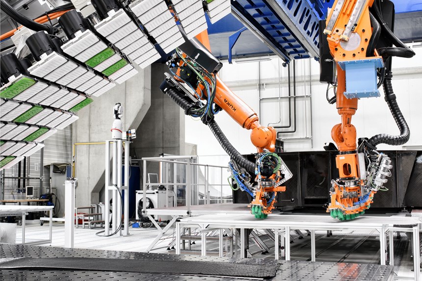
- Draping of large-cut structural plies where two robots collaborate, one per fabric edge, to pick up and create the target geometry of the mold to ensure conforming without wrinkles before placing.
- Accommodation for small, shaped plies up to 1.5 by 2.5 meters.
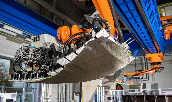
“For the cooperating robots, we developed end-effectors that contain six modules connected by spherical joints,” Larsen explains. “This allows the end-effector to deform, in a manner similar to a snake, conforming to the target geometry of the mold. Integrated heating devices activate the binder in the fabric as it is being transported and shaped, maintaining its 3D shape and position once placed.”
Automated draping and placement
For the small, shaped plies up to 1.5 by 2.5 meters, a second kind of gripper was developed that uses 127 modules equipped with vacuum suction for pick- up. “This gripper picks up material in a 2D state and then bends it to the target geometry,” Malecha explains. “It must decide which of the 127 modules it will hold firm and which it will let slide to transform the 2D ply to a 3D shape. So, it is very similar to how hands work to drape. We made many experiments and gained experience on where to hold and where to release. Force can be adjusted by how intense the modules grip on the material.”
Inline inspection. Optical sensors in the modular grippers monitored the draping process. After placing a ply, an end-effector combining a Leica T-Scan (Hexagon Manufacturing, Cobham, U.K.) and a camera-based fiber angle measurement system by Profactor (Steyr, Austria) inspect for quality. “We first measured fiber angles and compared to the CAD file,” says Malecha, “and then we measured the edges of each piece and checked its position versus the CAD file.”
Diagram of the types of cut-pieces and stringers applied to create the preform for the RPB demonstrator manufactured by DLR in the PROTEC NSR project. Source | Fig. 1 from “Highly Automated Manufacturing Process of Large Airplane CFRP Structures” by Marcin Malecha and Thomas Full, Center for Lightweight Technology (ZLP), German Aerospace Center (DLR). Photo Credit: German Aerospace Center (DLR) Institute of Structures and Design
Stringers and vacuum bagging. After completing the preform, eight stiffeners (stringers) were attached on top. For this task, the Multi Kinematic Gripper was developed and was also used to apply the vacuum bag auxiliary materials. This gripper comprises three small and independent 6-degrees-of-freedom (DOF) robots and a rigid arm, all mounted on the center flange of an industrial 6-DOF robot. Vacuum bagging auxiliary materials — peel ply, perforated release film and resin flow media (tool-side auxiliary materials) — were precut and prejoined, designed for where they were placed. “They didn’t have to be draped, just placed,” notes Malecha. The prefabricated semi-permeable membrane was applied in a semi-automated way via an end-effector with an “umbrella-like” mechanism, while placement of tacky tape and outer vacuum bag remained manual but could also be automated.
Cycle time and cost. For Malecha, the largest challenge was building the modular, artificial intelligence (AI)-based manufacturing execution system (MES) to monitor and control the process chain. “We had to build data management systems that could bring together quite different processes and then command them via the MES through one data exchange port,” he explains. “We can use them as they are needed on the fly, enabling more flexibility and wider use versus following a strict manufacturing order.”
The PROTEC NSR technology was validated by manufacturing a full-size demonstrator in January 2019, and achieving a maturity level of TRL 5-6 by mid-2019. Compared to the current state-of-the-art at PAG, this automated process chain cuts the cycle time of rolled fabric application by 58% and pick-and-place of cut plies by 50%. Manufacturing costs for these operations were reduced by 11.5% and 31%, respectively.
Thermoplastic RPB
“This project started in 2018 with PAG and Institut für Verbundwerkstoffe (IVW, Kaiserslautern, Germany) to show what is possible with thermoplastic composites in large parts and primary structures,” explains Dr. Stefan Jarka, project manager for Fast Lane RPB and expert on welding technologies at ZLP Augsburg. “An RPB is not really primary, because the mechanical requirements are not as high as a wing or fuselage, but it shows what is possible for large, flat, slightly curved structures. In just four months, we developed a demonstrator A320 RPB as an example of how to convert an existing aluminum structure to thermoplastic composites.”
This demonstrator used Cetex carbon fiber (CF) fabric/polyphenylene sulfide (PPS) organosheet (Toray Advanced Composites, Nijverdal, Netherlands) and resistance welding. A resistive element between the two surfaces being welded generates heat and remains in the welded structure. GKN Fokker (Hoogeveen, Netherlands) has used this technique for decades to produce aircraft landing gear doors and fixed leading edges. For this A320 RPB, the ZLP team used a CF resistive element instead of conventional stainless-steel mesh.
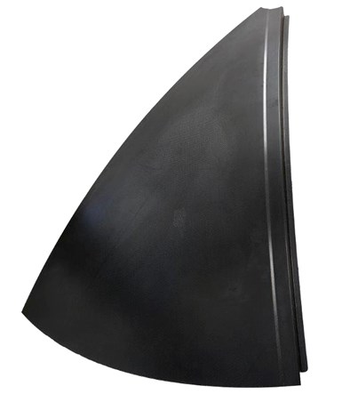
One of the eight CF/PPS petal sections welded together to form the thermoplastic composite RPB. Photo Credit: German Aerospace Center (DLR) Institute of Structures and Design
“The thermoplastic composite RPB was to be the same price or cheaper, but the material is much more expensive,” notes Larsen. Thus, lower production cost due to automation was key, as was the use of eight identical petal sections. “These sections were needed to form the double-curved shape of the part,” Jarka explains. “Thermoforming as one single part would require a very large press that would be too expensive. Thus, eight smaller sections were press-molded by the IVW using matched metal tooling and we assembled these using automated welding. The automation level for thermoplastic press-forming is higher than for thermoset composites. You are mostly using matched metal tooling, with high but constant temperature being the main issue, but this also makes the automated press cycle very fast.”
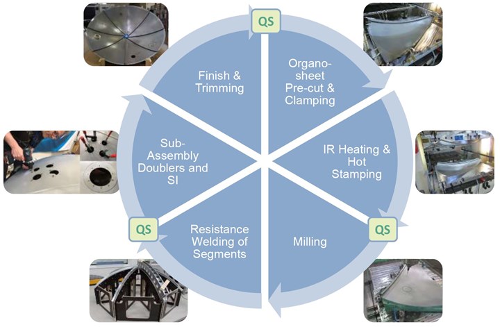
The overall process steps for the demonstrator RPB are shown in Fig. 2. “The welding process we used was not new,” says Jarka, “but had to be further developed to join the 1.5-meter-long [and 40-millimeter-wide] seams for the 3-meter-diameter part and integrate a quality inspection system. Components were first fixed into the right position using a positioning jig and then electrical energy was applied to generate the plastic melt in the weld zone.”
Fig. 2. Thermoplastic RPB process steps
Process steps used to produce eight sections (bottom) of stamp-formed CF/PPS organosheet that were then joined via resistance welding to form a demonstrator A320 bulkhead. Photo Credit: German Aerospace Center (DLR) Institute of Structures and Design
Integrating QA. “We tried thermography, both flash lamp- and ultrasonic-activated, but it’s not so easy to measure the welding zone with this,” Jarka explains. “Thermography is very fast, but it doesn’t easily tell you if you have good consolidation.” Instead, they used a standard test rig to make multiple welded samples, measuring current, voltage and temperature. “We then inspected them with ultrasonic testing (UT) and made correlations between process parameters and good consolidation,” says Larsen. “If we have good parameters, then we have a good part. We have also built a process simulation to compare the data we obtain during welding with the initial baseline we established.”
Automation and cycle time. “The whole process was very fast, on the scale of automotive parts,” says Jarka. “We achieved TRL 3 in our 2019 review and have since matured to TRL 4. We will achieve TRL 6 by the end of 2021.” Before the pandemic, PAG had indicated it would put the thermoplastic RPB into production by 2021. Though the future is now less clear, the thermoplastic RPB is still seen as enabling the “fuselage of tomorrow,” reducing weight from 41 to 35 kilograms, process and assembly time by 75% and overall part cost by more than 10%.
Comparing TS and TP composites
“The thermoplastic processes are so fast that you can be cheaper versus aluminum and even meet a production rate of 100 aircraft per month,” says Jarka. “The RPB is a good application for thermoplastic welding but also for automation,” says Malecha. “The dry fiber, liquid-molded RPB is more expensive to automate.”
“But that automation is interesting because you could achieve real gains by automating just some of the sub-processes,” says Larsen. “For example, with automating the auxiliaries, we could complete the vacuum bagging in about an hour, roughly 10 times faster than the manual process.” However, he concedes that cost is a major obstacle to implement such improvement. “The cost of the digital tools, robots and development is too much for one single part, such as the RPB. But if we could develop a modular approach where you could use this system for many parts, then this cost could be spread wider, making it affordable when calculated with the reduced time and labor.” ZLP has indeed achieved this, as explained in CW’s July 2020 feature: “Composites 4.0: Digital transformation, adaptive production, new paradigms.”
“There are not yet many comparisons between thermoset and thermoplastic composite structures,” says Malecha. “But we are beginning to compare thermoset and thermoplastic processes.” He notes the next goal is to show that thermoplastic weld lines have the properties required for aircraft wings and fuselages. And that performance must also be shown for large, integrated liquid molded wings, for example. This is exactly what the MFFD and WOT programs have set out to accomplish. And we await their results, as well as those from many other Clean Sky 2 and EC projects, to show the next steps forward.
Related Content
Composites manufacturing for general aviation aircraft
General aviation, certified and experimental, has increasingly embraced composites over the decades, a path further driven by leveraged innovation in materials and processes and the evolving AAM market.
Read MorePlant tour: Teijin Carbon America Inc., Greenwood, S.C., U.S.
In 2018, Teijin broke ground on a facility that is reportedly the largest capacity carbon fiber line currently in existence. The line has been fully functional for nearly two years and has plenty of room for expansion.
Read MorePlant tour: Albany Engineered Composites, Rochester, N.H., U.S.
Efficient, high-quality, well-controlled composites manufacturing at volume is the mantra for this 3D weaving specialist.
Read MoreTU Munich develops cuboidal conformable tanks using carbon fiber composites for increased hydrogen storage
Flat tank enabling standard platform for BEV and FCEV uses thermoplastic and thermoset composites, overwrapped skeleton design in pursuit of 25% more H2 storage.
Read MoreRead Next
Plant tour: Daher Shap’in TechCenter and composites production plant, Saint-Aignan-de-Grandlieu, France
Co-located R&D and production advance OOA thermosets, thermoplastics, welding, recycling and digital technologies for faster processing and certification of lighter, more sustainable composites.
Read MoreDeveloping bonded composite repair for ships, offshore units
Bureau Veritas and industry partners issue guidelines and pave the way for certification via StrengthBond Offshore project.
Read More“Structured air” TPS safeguards composite structures
Powered by an 85% air/15% pure polyimide aerogel, Blueshift’s novel material system protects structures during transient thermal events from -200°C to beyond 2400°C for rockets, battery boxes and more.
Read More


