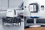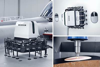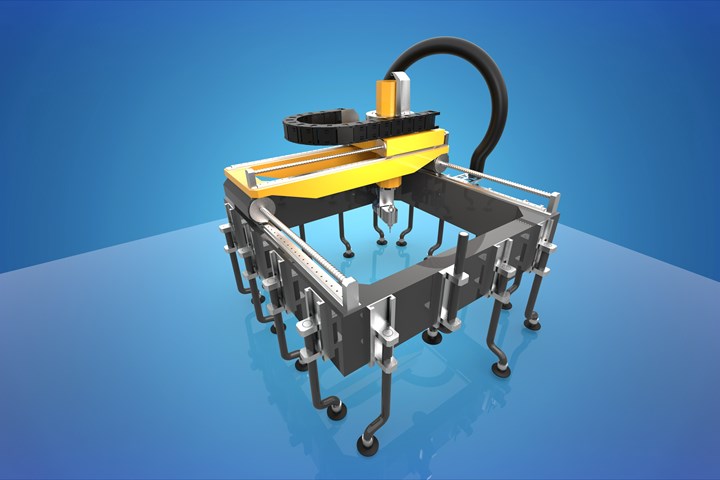
AGFM’s portable scarfing/composite repair system (PS/CRS) concept is developed for fast, on-site scarfing of damaged composite aircraft components. It also works together with NIAR-developed software to capture data for more accurate scarfing and patch development, and to create a digital thread of repair information about each part or aircraft. Photo credit, all images: AGFM
As aircraft manufacturers develop more and larger composite aircraft components, the need for reliable, on-site composite repair methods also grows. Composites repair can be complex, involving some method of manual or scanner-based inspection, removal via machining of the damaged portion of the part (a process often called scarfing), and patching with new material via methods such as mechanical connections or re-laminating via infusion.
Historically, many of these processes are done by hand — though automated repair technologies have been maturing for several years (see “Aircraft composite repair moves toward maturity”). For repair of large aircraft components such as wings and fuselages that cannot be easily moved to a repair shop, there are also several portable repair technologies on the market to speed the process.
American GFM (AGFM, Chesapeake, Va., U.S.), the U.S. branch of Austrian machine tool and composites manufacturing systems supplier GFM, and its partners are developing their own portable, automated system intended to be a complete, data-driven repair solution — combining inspection, scarfing and repair into one system, integrated and driven by digital twin technology.
These efforts, led by Frank Elliott, advanced initiatives coordinator at AGFM, have been in development since 2006, when AGFM began discussions with the U.S. Department of Defense (DOD), the National Center for Manufacturing Sciences (NCMS) and Tinker Air Force Base about ideas for automated composite inspection and repair. Elliott, who has served AGFM for more than 30 years, has carried his ideas for automated composite repair technology with him since the early days of his career in the industry. As a consultant working with Tinker Air Force Base on composite radome repair in the early 1990s, Elliott says, “I came up with some suggestions to go from all-manual processes and functions to certain automated processes, including eliminating the ‘manual tap test,’ which does not provide any digital data from which you can create CNC machining processes, and thus required manual defective or damaged material removal.”
Years later, Elliott brought his ideas for a data-driven CNC scarfing system to his position at AGFM. Since 2006, the AGFM team have worked on these ideas to prove out various iterations of its technology in projects with several partners, starting with automated inspection and repair preparation cells.
Proving out automated, integrated NDI/scarfing technology
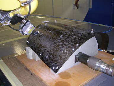
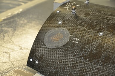
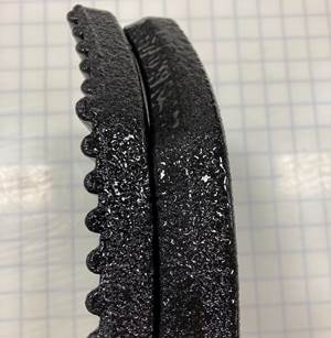
In one series of in-house tests, AGFM used its inspection and repair cell technology to scan a carbon fiber/BMI demonstrator component with incipient heat damage. Using the same machine head, the part was inspected via a laser scanner (top image) and milled to remove the damaged part of the component (bottom).
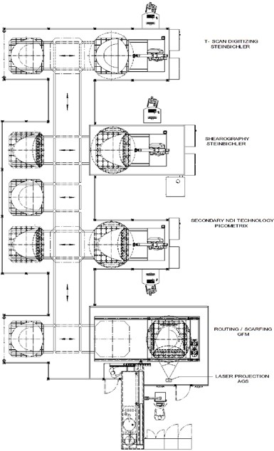
In 2011, AGFM demonstrated its DOD-funded inspection and repair preparation cell (IRPC) technology on a C-130 nose radome. First, the entire structure was placed into a shearography nondestructive inspection (NDI) chamber for laser inspection of the whole structure. This initial inspection suggested several areas of potential damage on the radome, which were then inspected more locally via an automated NDI laser inspection system mounted to an AGFM multiple-axis machine tool head scanning the surface of the part. Using data from both NDI scans, plus data from the surface digitizing, the scarfing was performed immediately using the same machine tool on which both the NDI system and the digitizing system were mounted.
In 2012, AGFM followed up the IRPC project with a self-funded project to build and demonstrate a repair preparation cell (RPC) for use in instances where inspection has already been done. For this project, AGFM used a five-axis, USR-60 machine tool with mounted scanner to capture digital surface data on the damaged areas of an engine nacelle cover prior to scarfing.
AGFM also conducted an in-house project using a carbon fiber/bismaleimide (BMI) composite component, using the integrated system to inspect, digitize and scarf areas of incipient heat damage on the part. Another project aims to develop a process for laser drilling extremely high quantities of perforation holes in acoustic panels for manufacturing and repairing engine nacelles. The combination of these and other in-house projects, spanning more than 10 years, led to a highly tested integrated process for NDI testing, digital data collection and automated scarfing.
Next steps: Portable composite repair
“In the past, both during and since our initial developments of IRPC and RPC systems, AGFM has been requested to consider developing a portable composite repair system with similar capabilities,” Elliott explains. Portability would allow the flexibility for on-site repair of aircraft components, or of other large structures that cannot be transported to a repair facility.
AGFM’s proposed solution is called the Portable Scarfing/Composite Repair System (PS/CRS). Along with designing a portable version of its inspection and repair preparation cells, AGFM has partnered with Wichita State University’s National Institute for Aviation Research (NIAR, Kan., U.S.) to, Elliott says, “create AGFM’s envisioned complete portable composite repair system, which will include all processes from determining location of defects/damage and digital surface scanning through scarfing, plus creating replacement material plug/plies and cure cycle. This is going to revolutionize the ever-growing composite repair needs of the advanced manufacturing industry, beginning with aerospace and defense.”
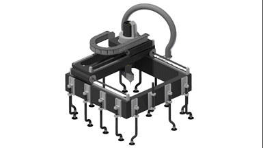
The portable version of AGFM’s integrated system is essentially four pieces: A square frame with vacuum pods, the milling system with attached spindle unit for scarfing, an electronic and CNC box for human machine interface (HMI) and a vacuum dust extraction system including a hose. The machine has a footprint of 5.4 feet x 5.4 feet, and is 4.75 feet tall. It’s also designed for a linear axis speed of 590 inches per minute maximum.
The machine can be transported to a site for scanning and scarfing of parts that are too large to move from the facility, or it can be attached directly onto an aircraft surface via vacuum pods. The spindle and frame sections of the PS/CRS would be joined as a single assembly prior to being picked up and transported to the part. Elliott says one option for lifting the PS/CRS system onto an aircraft might be a portable crane system — AGFM is working with specialty ground support equipment (GSE) supplier Field International (Poole, U.K.) to develop a transportable lifting arm concept capable of handling systems such as the PS/CRS.
To use the system, first, the unit must be placed over the section of the part needing inspection and repair. A laser scanner — either one that the user already may have, or one can be included with the PS/CRS — inspects the part and reveals the defected areas, saving the data as digital files. The CNC system is easily programmed for a custom scarf area, and the scarfing is performed. The PS/CRS is then removed for repair of the part with new material.
In addition to the PS/CRS system, AGFM has also been working to develop a more accurate, digitized process for repair patch development. To manually make a repair patch, Elliott says, typically the pattern is traced by hand on paper or a transparent medium like Mylar placed over the damaged part to get as close of an outline of the shape as possible. Then this pattern is used to cut the new material for the patch. “This process is time-consuming, and only approximates the outline at best,” he says.
The PS/CRS system comprises four parts assembled together: the spindle and frame (pictured), CNC control system (not pictured) and dust extraction system (not pictured).
AGFM has partnered with NIAR on digital software to replace this manual process. NIAR’s Sustainment Lab and Digital Twin Lab have been working with the U.S. Air Force to mature digital twin technology for repair of aging military aircraft. They take apart military planes, scan them into software they have developed and then digitally reassemble the pieces. “The insights gained through the digital assembly provide valuable data to those who might work to maintain and repair similar aircraft in the future,” Elliott says.
Based on this work, NIAR has patented a methodology and software for generating a repair patch for a damaged area of composite structures based on 3D scans of the damaged area. The on-site repair team scans the part with help from NIAR software, which stores the data for use in programming the CNC scarfing system on site. This data can also be used by AGFM or an off-site team to guide laser-projected ply cutting of the material for the patch, as well as a 3D-printed mold for patch layup. If built off site, the finished patch would then be sent to the customer for bonding onto the part.
One of the most important things about this process is that it leads to a digital thread of repair data about that aircraft or part. Elliott notes, “The generated reports will have all the information saved for verification by regulatory agencies as needed. The digital thread that is developed will also be essential to ensure cases in which there have been previous repairs.” In addition, the often week-long lead time for repair may be shortened to a few days, he says.
Currently, AGFM is talking and meeting with customers, and plans to start commercializing the technology soon, Elliott says. In the meantime, the company is also working on additional research developments, including R&D trials of ultrasonic machining and welding for thermoplastic part repair.
For more information, contact Frank Elliott at elliott@agfm.com or Jeswin Joseph, program and research manager at NIAR/WSU, at JeswinJoseph@niar.wichita.edu.
Related Content
Industrializing additive manufacturing in the defense/aerospace sector
GA-ASI demonstrates a path forward for the use of additive technologies for composite tooling, flight-qualified parts.
Read MoreUS Air Force selects Integris Composites ballistic body armor
Cratus Wave armor is thin, lightweight and reduces heat stress, providing buoyant personal protection for the 582nd Helicopter Group.
Read MoreFarnborough Airshow 2024 brings together aerospace innovation, collaboration
The week-long international airshow provided a hub for new announcements made by Boom Supersonic, Airbus, Boeing, GKN, GE, ZeroAvia, Eve, Bell, VoltAero, Eve and Lilium. CW has compiled several below.
Read MoreMATECH C/ZrOC composite is deployed in hypersonic aeroshells
Ultra high-temperature insulating CMC targets hypersonics, space heat shields and other demanding applications, tested up to 2760°C under extreme stagnation pressures.
Read MoreRead Next
Aircraft composites repair moves toward maturity
New technologies seek to address the challenges MROs will increasingly face in the age of commercial airliners with composite airframes.
Read MoreAll-recycled, needle-punched nonwoven CFRP slashes carbon footprint of Formula 2 seat
Dallara and Tenowo collaborate to produce a race-ready Formula 2 seat using recycled carbon fiber, reducing CO2 emissions by 97.5% compared to virgin materials.
Read MorePlant tour: Daher Shap’in TechCenter and composites production plant, Saint-Aignan-de-Grandlieu, France
Co-located R&D and production advance OOA thermosets, thermoplastics, welding, recycling and digital technologies for faster processing and certification of lighter, more sustainable composites.
Read More

.jpg;width=70;height=70;mode=crop)
