
Off-grid turbine: Helix in the wind
This new composite twist on the vertical-axis wind turbine makes no small impact on the private power market.

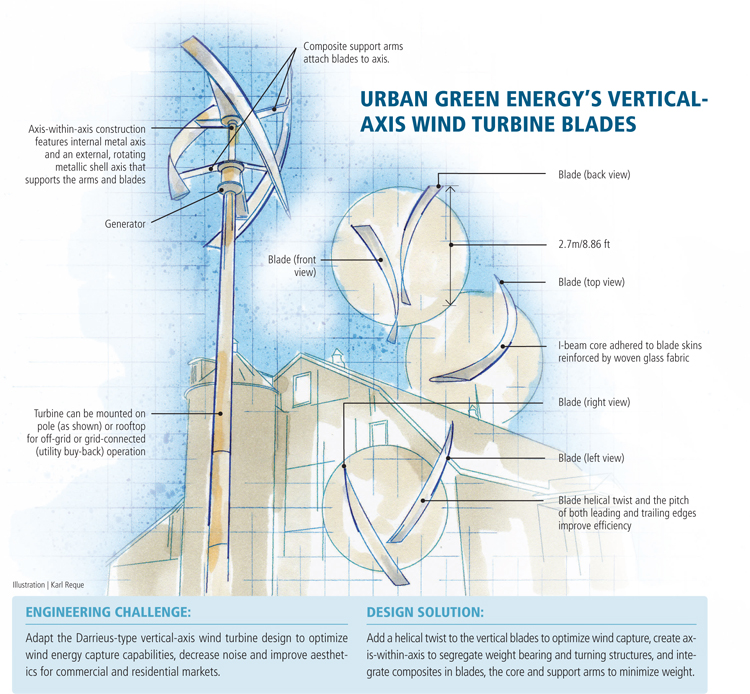
Urban Green Energy's Vertical-axis Wind Turbine Blades Illustration: Karl Reque
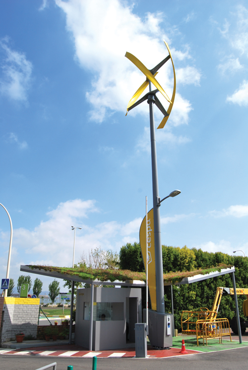
Urban Green Energy (UGE, New York, N.Y.) entered the vertical axis wind turbine (VAWT) market in 2008, chose the Darrieus design type, and then modified it with helical blades to optimize wind capture, efficiency and aesthetic appeal. Shown here is the 1-kW eddyGT that powers this electric-vehicle charging station on the campus of environmental services company CESPA SA (Barcelona, Spain). Source: UGE
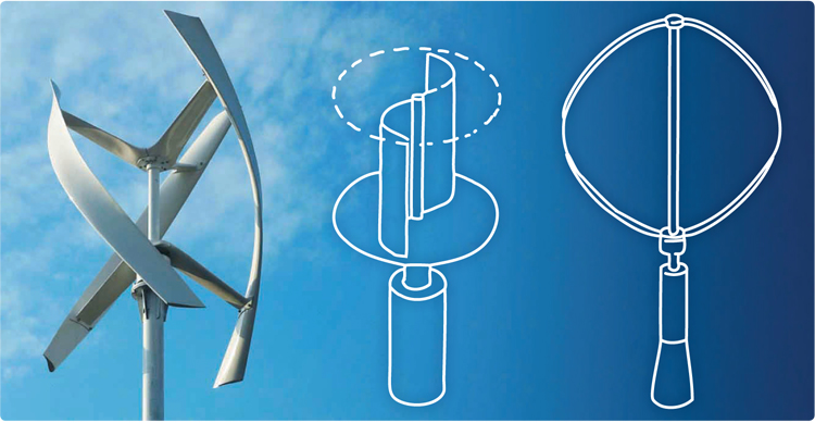
Manufacturers of VAWTs typically employ a turbine design type that is a variation of one of two categories. The Savionius type (center) uses a series of air scoops attached to the vertical axis. The Darrieus type (right), which UGE chose, features two or more parabolically shaped air foils oriented in the same direction as the turbine axis. UGE’s innovation is the helical blade design (left), which adds aesthetic appeal and enhances wind-capture. Source: UGE


Engineering Challenge:
Adapt the Darrieus-type vertical-axis wind turbine design to optimize wind energy capture capabilities, decrease noise and improve aesthetics for commercial and residential markets.
Design Solution:
Add a helical twist to the vertical blades to optimize wind capture, create axis-within-axis to segregate weight bearing and turning structures, and integrate composites in blades, the core and support arms to minimize weight.
As current commercial wind turbine capacities race past 2 MW and head for 3, 5 and 7 MW, it’s hard to remember that there was a time when wind energy systems weren’t so large — when blades and towers were shorter and when a high-end turbine generated 100 kW of power. But that was 20 years ago, and economies of scale have since dictated growth to increase wind energy capture capabilities, particularly as the industry looks to offshore locations.


In the wake of the race for size, the wind energy industry left a void in the market for smaller-capacity turbines designed to serve off-grid business, residential and industrial applications. Into this gap, over the last decade or so, have stepped a variety of small-capacity wind turbine manufacturers. Although many of these producers have followed the large-turbine model and employ horizontal axis turbines, some have opted for vertical-axis wind turbines (VAWTs).
VAWTs present their own challenges in terms of wind blade design and wind energy capture strategies, but the vertical axis also provides greater flexibility in terms of size, shape and form of the blade. The VAWT market, in general, is replete with imaginative blade designs that aim not only for efficient energy capture but also strong aesthetics because of the need to appeal to consumer and business interests in highly visible applications.
There are two fundamental VAWT blade designs from which manufacturers can choose: Savonius and Darrieus (see comparison photo). A Savonius design is characterized by two or more scoops attached to the turbine’s vertical axis. A Darrieus system comprises two or more airfoils, sometimes with a parabolic shape, attached to the turbine’s vertical axis. Most VAWT manufacturers have, at some point, picked either Savonius or Darrieus as the primary blade design type and then developed variations that, ideally, increase wind capture efficiency and help produce a viable, sustainable product.
This was the position in which Urban Green Energy (UGE, New York, N.Y.) found itself in 2008. The company was looking to enter the small wind VAWT market, evaluated the Savonius and Darrieus designs, and decided that Darrieus was the best bet. Nick Blitterswyk, UGE’s CEO, remembers, however, that the lack of research and development in the small wind market following the scale-up of commercial turbines left open many questions about optimum VAWT blade design strategies for good aerodynamics.
“We wanted to make a turbine that is efficient, quiet, durable, has little vibration and looks good,” Blitterswyk recalls. “But there was just not much data available about VAWT blade design and how well they perform in different wind conditions.”
UGE’s first task, then, was to develop a basic design and then prototype it for testing. The company opted for a design that has become the firm’s trademark: three helical blades curve around the shell axis, and each blade is attached to the shell axis by two arms that are bonded to the back of the blade. Although UGE intended from the start to employ composites in blade construction, Blitterswyk says the company fabricated its first prototype from metal strictly to assess design viability. “The first prototype was a basic airfoil with relatively short chord length. It actually didn’t look that good,” he admits. “It had lots of metal with the blades connected at the top and bottom.” UGE also discovered that some of its assumptions about blade design were wrong. “Without giving away too much, I will say that when we first made this prototype, we did so based on some data from other turbines on the market. We found that claims of other suppliers about turbine capability were not accurate,” he says.
Testing of the first prototype was conducted at a facility near Beijing, China, where UGE was looking to do its manufacturing. The trials, Blitterswyk notes, ranged from the conventional (wind tunnel) to the unconventional (box fan; turbine mounted in pickup truck bed). All of this work led to several design changes in the second and third prototypes — changes that have persisted in UGE’s current products.
Most notably, says UGE engineer Katrina Prutzman, the company opted for a unique two-axis design, “one axis inside the other to even out the load.” The interior axis is metallic, emerges from the generator at the base of the turbine and bears most of the load of the blades. Surrounding this is the shell axis, which is also metallic and rotates around the primary load-bearing axis. It rides on sealed bearings to maintain easy turning capability and forms the structure to which the blades are attached.
The second and third prototypes also saw UGE fine-tune the design of the helical blades, with subtle changes to the pitch of the leading and trailing edges, the degree of twist in the helix, the blade length and the blade width. Most of this design work, says Prutzman, was and is done with SolidWorks from Dassault Systèmes (Waltham, Mass., and Paris, France). More testing ensued, and by early 2009, says Blitterswyk, the design was finalized and UGE was ready to begin manufacturing.
The first UGE turbine launched commercially was the eddy, a 600W system with helical blades about 2m/6.6 ft long. This was followed by the eddyGT, one of UGE’s best-sellers. Blitterswyk says UGE first considered carbon fiber for turbine blade fabrication but eventually migrated to glass fiber. The eddyGT blades employ a fairly simple architecture, consisting of a foam core surrounded by a glass fiber laminate on each side. The glass, primarily a dry woven fabric, includes some unidirectional material around attachment points for added strength. The fabric is supplied from a source near Beijing. It is hand-placed in the tool and then vacuum-bag infused. “I don’t know if I ever felt like we were bumping up against a material limitation with composites,” Blitterswyk recalls. The limitation, he says, was encountered on the manufacturing floor.
The goal from the start, he notes, was to find a composites-capable manufacturer near UGE’s assembly facility outside Beijing and have that company mold and supply finished blades and outer axis structures. However, Blitterswyk says the complex helical curve of the blades proved particularly challenging to the supplier. Not only was proper placement of the glass fiber fabrics important, but placement had to be done on a surface replete with curves and slopes. This presented a challenge that the contractor was unable to meet.
Blitterswyk says UGE decided, at that point, to forgo outsourcing. The company brought all of its composites manufacturing in-house and developed a robust process that includes cutting required fabric shapes on a cutting table, hand placing fiber forms and performing consistent, repeatable resin injection via vacuum bag infusion.
As UGE’s product line expanded and turbines and blades increased in size, Prutzman says designs were modified to reduce blade weight and increase strength. This was accomplished primarily by replacing the foam core with an I-beam core. Fabricated from the same glass/polyester material used in the skins, the I-beams are laid up and molded separately. The blade skins, also molded separately, are then adhesively bonded to the I-beam.
For the eddyGT turbine, the metallic support arms are attached to the blade with molded-in metallic nuts, into which bolts are screwed. On larger blades for later turbine models, the support arms were converted to glass/polyester composite.
To date, UGE has developed four systems, including the eddy (600W), the eddyGT (1 kW), the UGE 4K (4 kW) and its largest turbine, the UGE 9M, a 10 kW system that features 9m/29.5 ft blades. Blitterswyk says each turbine represents some iteration in blade design evolution. “We find that there is still a lot of improvement that can be made in efficiencies,” he notes.
UGE has placed turbines in more than 70 countries and has seen revenue more than double each year for the past three years. The company’s top markets, says Blitterswyk, are commercial (BMW, the Hilton Hotels chain and General Electric Co. are customers) and off-grid telecom. The latter is most common in developing countries where the power grid infrastructure can’t supply power to remote signal towers for mobile phone and other communication networks. UGE’s turbines provide a small, affordable way to meet the this need. In 2012, UGE already has sold more than 1,000 turbines. The company expects to double that quantity in 2013 and will double the size of its manufacturing facility near Beijing, China.
It’s likely that the VAWT market, like the commercial wind energy systems that came before, will continue to scale up to meet a variety of commercial and residential energy needs. Expect the helical Darrieus to continue its own evolution in the process.


Related Content

Novel dry tape for liquid molded composites
MTorres seeks to enable next-gen aircraft and open new markets for composites with low-cost, high-permeability tapes and versatile, high-speed production lines.
Read More
One-piece, one-shot, 17-meter wing spar for high-rate aircraft manufacture
GKN Aerospace has spent the last five years developing materials strategies and resin transfer molding (RTM) for an aircraft trailing edge wing spar for the Airbus Wing of Tomorrow program.
Read More
Materials & Processes: Tooling for composites
Composite parts are formed in molds, also known as tools. Tools can be made from virtually any material. The material type, shape and complexity depend upon the part and length of production run. Here's a short summary of the issues involved in electing and making tools.
Read More
PEEK vs. PEKK vs. PAEK and continuous compression molding
Suppliers of thermoplastics and carbon fiber chime in regarding PEEK vs. PEKK, and now PAEK, as well as in-situ consolidation — the supply chain for thermoplastic tape composites continues to evolve.
Read MoreRead Next

Small wind gets big
Massive growth, complex blade designs reopen challenging market in wind energy niche.
Read More
Small wind: Green energy gets greener
Kilowatt-rated vertical axis wind turbines supply green electric power where utility-scale turbines can’t.
Read More
Composites end markets: Energy (2024)
Composites are used widely in oil/gas, wind and other renewable energy applications. Despite market challenges, growth potential and innovation for composites continue.
Read More