
Anisotropic wind blade design expected to reduce wind-energy costs
Deliberately unbalanced laminate produces smoother power input from adaptive wind blades


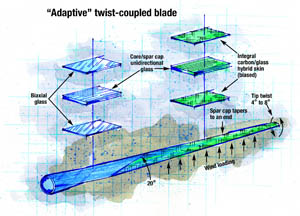
Source: Illustration: Karl Reque
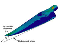
Source: GECExtensive finite element analysis ensured that the adaptive blade design would successfully manage stresses created under wind loading.
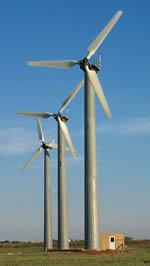
Source: GECThe fixed-pitch, fixed-speed test turbines at the U.S. Dept. of Agriculture's Bushland, Texas test facility will demonstrate the impact of twist coupling on blade performance, but even greater results are anticipated when such adaptive blades fly on variable-pitch, variable-speed turbines
To lower the cost of energy from wind turbines, designers have focused on the power-generating capacity of each turbine. They have raised tower height to place turbines in stronger winds and lengthened blades to capture more wind. But as these strategies have begun to reach the upper limits of practicality, designers are exploring the use of carbon fiber as a means to further push the design envelope and decrease the cost of energy. Compared to conventional all-fiberglass designs, composites that replace some of the glass with carbon fiber reinforcements can produce the same level of performance using less fiber and resin, and therefore significantly reduce blade weight. More importantly, a glass/carbon hybrid or all-carbon blade will increase blade stiffness. Reduced weight and increased stiffness improve blade aerodynamics and decrease the loads imposed by the blades on the tower and hub. A design that incorporates carbon fiber also can make power input from the blades as smooth and consistent as possible, improving energy efficiency. This last accomplishment exploits a characteristic unique to fiber-reinforced materials: the ability to produce a non-symmetric laminate and "anisotropic" properties, so that the blade twists into stronger winds to reduce transient loading.
A study funded by Sandia National Laboratories (Albuquerque, N.M., U.S.A.) has produced an "adaptive" blade of this type, which promises to reduce the cost of energy from a 1.5-MW turbine by about 2 percent. This reduction is significant in energy production, where a move from 5 cents to 4.9 cents per kwh, for example, makes wind energy that much more competitive with fossil fuels. The study's design team is led by Global Energy Concepts LLC (GEC, Kirkland, Wash., U.S.A.), with members TPI Composites (Warren, R.I., U.S.A.) and MDZ Consulting (Kemah, Texas, U.S.A.). Prototype 9m/29.5 ft blades, currently being fabricated, will soon be installed for proof-of-concept tests at the U.S. Dept. of Agriculture's test facility in Bushland, Texas, U.S.A. If these adaptive blades enter widespread use, the wind energy market will be the first to extensively employ an anisotropic design.


Anisotropy applied
When wind rises above the designed speed of today's active utility-size wind turbines, typically 13 to 15 m/sec (29 to 33 mph), a pitch-control system allows the blades to make use of as much wind as possible, but "shed" the excess in high winds to avoid damage to the turbine system. A motor mounted in the rotor hub physically rotates the blades, changing the angle of attack of the airfoil. Pitch control systems are generally effective in adapting blade angle to gradual changes in wind speed, but the pitch actuators are too slow to respond to gusts. The "adaptive" blade's anisotropic laminate design helps the pitch control system maintain a steadier flow of electrical power under these sudden, transient and localized wind conditions. Most composite laminates are balanced, or mirrored, meaning that the fiber loading at a given angle in a ply schedule is matched with the same loading at the opposing angle; for example, +45° and -45°. When these balanced laminates experience an axial bending force, they respond uniformly along their axes. In contrast, when an unbalanced laminate -- where fibers at a given angle are not matched by opposing fibers -- is subjected to the same axial bending force, it will translate some of the force to the off-axis direction. As a result, the laminate will twist around that axis.
This is precisely the response designed into the Sandia adaptive wind blade. As wind speed goes up, increasing the bending force on the blade, the blade responds by twisting along its longitudinal axis and taking a lower angle of attack into the wind, which, in turn, reduces the bending load. Adaptive blades therefore also are called twist-coupled blades. "With twist-coupling," says Dayton Griffin, the GEC wind energy consultant who is heading up the adaptive blade project, "you can keep the good, steady power-production part of wind behavior, and smooth out unwanted peaks in loading." But this theoretical promise, he continues, is challenging to implement practically, especially at a reasonable cost. "Bend-twist characteristics are difficult to achieve while maintaining necessary blade strength and overall structural efficiency of the materials."
Well-placed bias
To put twist-coupling theory into practice, the GEC team first had to decide where to place the unbalanced, or "bias," carbon -- in the blade skins, in the spar caps, or in both? (The spar is a box-beam structure running longitudinally along the blade length, sandwiched between the outer skins of the blade. The spar caps typically are integrated into the skins, and webs span the space between the skins to complete the box shape.) While at least one other blade development group places bias plies in the spar cap (see CT April 2004, p. 26.), the GEC team has elected to incorporate the bias carbon into the blade skins. Griffin points out that because the spar cap does not span the entire width of the blade skin, bias in the cap would end abruptly at the spar-cap edge. Stresses at this discontinuity would have to traverse the epoxy matrix, which the design team concluded would be a poor load path for the primary bending loads. "Unidirectional tape along the spar-cap edge would improve the load path, but it also cuts into the twist-coupling response very quickly," Griffin notes.
Of course, bias fibers also come to an end when placed in the skins, at the leading and trailing edges. However, these terminations are near the neutral bending axis of the blade, where axial strains and corresponding stress levels are low. "So the GEC design concept is intended to keep the magnitude of stress discontinuities small," Griffin summarizes, "and ensure that the discontinuities do not occur along a primary load path."
Promising on paper
Because the design variables for an adaptive blade are all interrelated, the GEC team conducted a parametric study, which modifies each of the variables in numerous combinations to identify a set of optimal values The study, which used the ANSYS (ANSYS, Inc., Canonsburg, Pa., U.S.A.) finite element program to examine the model on a layer-by-layer basis, showed that a 20° bias provides the best twist-coupling while maintaining good structural properties. Initial analysis of the 9m/29.5 ft blade design predicted up to a 4° twist of the blade tips under normal operation in turbulent winds, and 8° twist for a 50-year extreme wind. Twist-coupling therefore reduced predicted fatigue loads in the blade and tower by 6 to 10 percent. This analysis was based on the particular turbine on which the blade will be tested, which offers fixed blade pitch (no pitch control) and fixed rotational speed. However, twist-coupling is expected to be much more effective when used on more advanced turbines. In addition to pitch control, most newer turbines also vary rotational speed. When wind falls below the turbine's rated speed, the variable-speed feature controls torque in the rotor to maintain the optimal ratio of blade-tip speed to wind speed. The result is peak efficiency in slower winds. Recent modeling of the 9m/25.9-ft twist-coupled prototype in a variable-pitch, variable-speed configuration predicted reductions in both peak and fatigue blade bending loads ranging from 17 to 28 percent. Simulations predicted tip rotation angles of up to 6° under normal operation in turbulent winds.
Materials selection
Study participant TPI evaluated the bias ply layup concept's manufacturability, looking at a range of fabric styles and resins to select those best suited to its SCRIMP (the Seemann Composites Resin Infusion Molding Process) vacuum infusion molding technology. TPI selected a Huntsman Advanced Materials (Brewster, N.Y., U.S.A.) epoxy resin based on a combination of infusibility characteristics and mech- anical properties. For the fabric, TPI looked for carbon-fiber straightness and good infusibility. "That's a tough combination to find," says Griffin. Stitching can cause perforations and bunching of carbon tows, he notes, which tends to improve infusibility at the cost of introducing local fiber waviness. "So there are technical challenges in obtaining good com- pressive strength from commercial carbon fibers in a low-cost manufacturing process." Ultimately, the team selected a stitched nonwoven 800-gsm triaxial fabric from SAERTEX USA LLC (Mooresville, N.C., U.S.A.) which consists of a 500-gsm layer of 0° T-600 carbon, supplied by Toray Carbon Fibers America Inc. (Flower Mound, Texas, U.S.A.) between two 150-gsm layers of fiberglass at ±45°. For the prototype, to orient the carbon at 20°, the glass layers in the triaxial bias ply will shift to +65° and -25°, but Griffin reports that this orientation still adequately manages shear loads. The rotated fabric also means that the edge of the bias ply forms a 20° angle along the blade's span, which gradually introduces the twist-coupling component along the span.
Because carbon fiber has a higher modulus than glass, the bias ply provides more axial stiffness than a standard nonwoven biaxial (±45°) fiberglass ply. This outcome produced two modifications from the standard blade design. First, in places where the triaxial bias fabric is included in the laminate, it directly replaces the biaxial fiberglass. Second, in this design, the blade skins can carry more of the bending load than conventional skins do, so the spar cap can be shorter. In the GEC design, the spar caps taper off and end about 2.7m/9 ft from the blade tip, so that the bending loads are carried entirely by the biased skins in the outer 30 percent of the blade span. (The smaller spar, Griffin points out, would not be implemented in larger utility-size blades because their greater structural demands increase the risks associated with such an aggressive design feature.)
The blade's skin construction is intended to deter crack propagation and provide sufficient impact protection. In the portion of the blade's span where there is no spar cap, balsa core is 6.35 mm/0.25 inch thick. To form the spar caps, unidirectional fiberglass substitutes for the balsa. One ply of standard biaxial fiberglass is positioned on either side of the core (or spar cap) from the blade root outward, until the ply of bias-carbon triaxial fabric commences. On the exterior of the blade, a 0.38-mm/0.015-inch-thick layer of random-mat fiberglass finishes the laminate schedule. Thus, the laminate schedule from exterior to interior of each blade skin includes one random-mat ply, one layer of either biaxial glass or the triaxial fabric, the balsa core or spar-cap glass, and another layer of biaxial glass or triaxial fabric. The dry laminate for each blade-skin half is infused in a SCRIMP mold. Spar webs are infused separately with the same epoxy. The blade pieces are then bonded together with Plexus MA 500 adhesive (ITW Plexus, Kettering, Northants, U.K.).
Once TPI's fabric and resin selections were made, the design team updated the previously analyzed blade structural models and evaluated static strength, fatigue strength and blade-tip deflections with satisfactory results. But Griffin believes that analysis alone has been taken as far as it can. "We can do just so much simulation," he says. "Then we have to build a testable structure."
The proof is in the field
In addition to flight testing in Texas, the adaptive blades' strength, stiffness, and twist-coupling will be characterized by structural testing at the National Wind Technology Center (Boulder, Colo., U.S.A.). While Griffin and his team anticipate good results, they emphasize that this blade culminates primary, not commercial, research. "It is anticipated that significant lessons remain to be learned concerning the manufacturing and structural performance of these blades," says Griffin.
Should the adaptive blades demonstrate their practical value, future developments will optimize cost of energy, validate the design for certification and address other commercialization issues. While the adaptive blade uses carbon only for twist-coupling, the GEC team also has built and tested a blade with a carbon spar. Savings from an adaptive blade combined with the carbon spar could easily justify the costs associated with commercial development.


Related Content

Materials & Processes: Fabrication methods
There are numerous methods for fabricating composite components. Selection of a method for a particular part, therefore, will depend on the materials, the part design and end-use or application. Here's a guide to selection.
Read More
Composite resins price change report
CW’s running summary of resin price change announcements from major material suppliers that serve the composites manufacturing industry.
Read More
Materials & Processes: Composites fibers and resins
Compared to legacy materials like steel, aluminum, iron and titanium, composites are still coming of age, and only just now are being better understood by design and manufacturing engineers. However, composites’ physical properties — combined with unbeatable light weight — make them undeniably attractive.
Read More
Novel composite technology replaces welded joints in tubular structures
The Tree Composites TC-joint replaces traditional welding in jacket foundations for offshore wind turbine generator applications, advancing the world’s quest for fast, sustainable energy deployment.
Read MoreRead Next

Big Blades Cut Wind Energy Cost
Rapid growth rate of composite-intensive conversion systems drives market competition and innovation.
Read More
From the CW Archives: The tale of the thermoplastic cryotank
In 2006, guest columnist Bob Hartunian related the story of his efforts two decades prior, while at McDonnell Douglas, to develop a thermoplastic composite crytank for hydrogen storage. He learned a lot of lessons.
Read More
CW’s 2024 Top Shops survey offers new approach to benchmarking
Respondents that complete the survey by April 30, 2024, have the chance to be recognized as an honoree.
Read More