Composites in commercial aircraft engines, 2014-2023
The drive to boost aircraft operating efficiency continues to fuel adoption of polymer matrix composites in jet engines.
Aircraft are creatures of economics. Commercial transport planes whisk passengers and cargo around the world in hours, but only if they generate direct profit for the airlines that fly them. Business jets profit commercial enterprises, albeit more indirectly, by doing the same for growth-conscious corporate executives. Not subject to profit/loss evaluations, military aircraft nonetheless transport troops and equipment and provide fast, far-reaching armed defensive capabilities on the strength of profits hard won by those who pay taxes, tariffs and duties to the governments that field them. Although they vary dramatically in capacity and capability, these flying machines have in common that operating them poses an increasing — and potentially unsustainable — expense to their owners.
Today, no single aspect of aircraft operating cost looms as large as — or is more easily addressed than — fuel consumption. Since 1990, the cost of jet fuel has risen at an average annual rate of 7.7%. As a result, it’s become the dominant cost center, particularly for commercial air carriers. At the turn of the millennium, says the International Air Transport Assn. (IATA, Montreal, QC, Canada), fuel accounted for 13-15% of direct operating cost. By 2006, it had soared to nearly 30%. At present, fuel represents 33-40% of global airline expenses and, even at somewhat moderated cost inflation, could soon climb to 50% or more.
In response to the concerns of commercial carriers, aircraft OEMs have devoted decades of research to reducing the cost of aircraft operation and ownership. These efforts have resulted cumulatively in some significant improvements. Since 1980, the average fuel burn per aircraft seat-km has been reduced by the following percentages:
• Regional turboprops 22%
• Regional jets 35%
• Single-aisle jets 35%
• Twin-aisle jets 27%
• Jumbo jets 9%
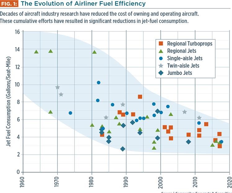
Continuing advances in aircraft and engine design are expected to make the newest versions of some of the most successful aircraft designs — commercial single-aisle transports (110-210 passengers) — nearly 50% more efficient than comparable aircraft introduced in the 1980s (see Fig. 1, at left). Examples include the upcoming Airbus A320neo, the Boeing 737 MAX and the Bombardier CSeries.
On the strength of additional savings strategies, IATA reports that between 1990 and 2012, its airline members have been able to improve their overall efficiency by 46% — significantly more than the per-aircraft efficiencies noted above. Some of the additional gains come from enhanced operational practices. The replacement of older aircraft in airline fleets with newer models with improved aerodynamics and more efficient engines has been the greatest aid to airline efforts to avoid billions of dollars in fleet fuel costs. This is one reason that commercial transport OEMs have been able to continue to increase production and sales over the past several years, despite trying economic conditions.
Efficiency drives design
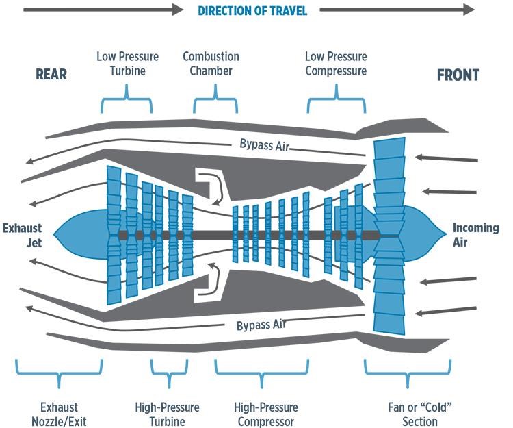
The jet engines market spans a wide range of products that generate from 2700 N-m to 163,000 N-m of thrust. Generally speaking, those covered in this outlook are in the sub-classification of turbofans. Although there are many variations, turbofan engines feature a large fan section mounted on the front of a core turbine, with an additional turbine in the rear, all connected by a driveshaft (see Fig. 2).
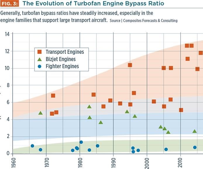
The turbofan generates thrust from two sources, the fan segment and the core turbine. Some of the incoming air captured at the engine inlet is fed into the core turbine’s low- and high-pressure compressor stages and on into the combustion chamber where the compressed air and fuel are mixed and ignited. As the resulting high-temperature gas expands, it turns the rear-mounted high- and low-pressure turbines that drive the front fan and compressor and then provides propulsive force as it exits the exhaust jet. The majority of a turbofan’s thrust, however, is the result of incoming air that is diverted around the compressor and turbine. The difference in the volume of air that bypasses the compressor vs. the air delivered to it is expressed as the “bypass ratio.” Bypass thrust does not require direct fuel burn. In the quest to improve operating costs, therefore, engine manufacturers have steadily increased bypass ratios, particularly in the engine families that support large transport aircraft (see Fig. 3). In general, the greater the bypass ratio, the better the fuel efficiency, especially at subsonic speeds.
Larger bypass ratios, however, result in larger fan sections and, in turn, heavier turbofans. The GE Aviation (Cincinnati, OH, US) CF6 engine family, for example, entered service in 1973 with a bypass ratio of 5:1. The CF6’s fan section accounts for 20% of total engine weight (~4,090 kg). GE’s new GEnx turbofan, which produces about the same amount of thrust, has a bypass ratio of 10:1. Its fan accounts for 30% of the engine’s 5,807-kg weight. Each kilogram added to the fan section necessitates 2.25 kg of extra support structure in the engine and the aircraft wing.
Design drives composites
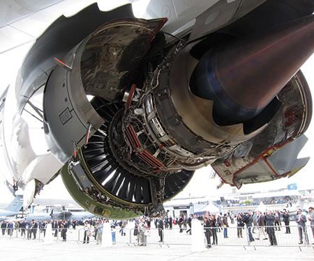
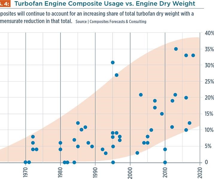
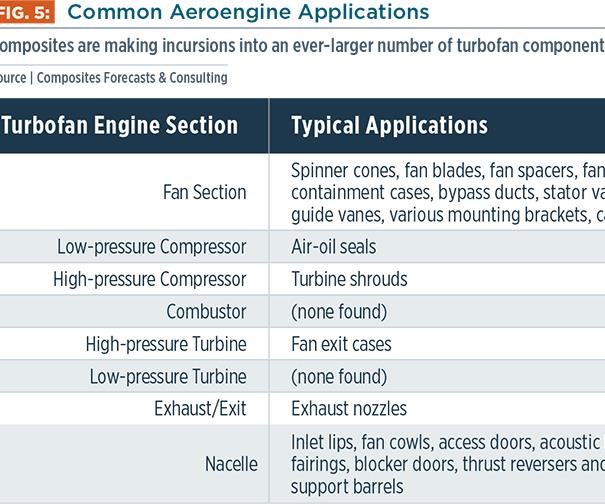
To mitigate weight increases, aeroengine manufacturers have replaced metal with composites (see Fig. 4). Throughout the 1980s and 1990s, the application of composites in aircraft engines was relatively limited. More than half of the total composite volume was directly associated with nacelle components, such as thrust reversers, acoustic liners, cascades, blocker doors, radial drive fairings and cowlings. On some models, aramid fibers (often in the form of dry-fiber belts) were used to reinforce aluminum fan cases. Composite nose cones, a variety of air ducts and engine air-oil seals were fairly common as well (see Fig. 5).
When it entered service in 1995, GE’s GE90 engine applied many more advanced materials and resin transfer molding (RTM) processing to introduce a number of new composite components — most notably, large fan blades made from hundreds of plies of intermediate-modulus carbon fiber prepreg. Since then, composite blades, fan containment cases, bypass ducts, stator vanes and a host of less glamorous detail components and brackets have become common not only in commercial jets but also in business and military aircraft.
Composites flyaway outlook
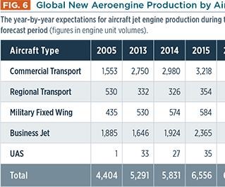
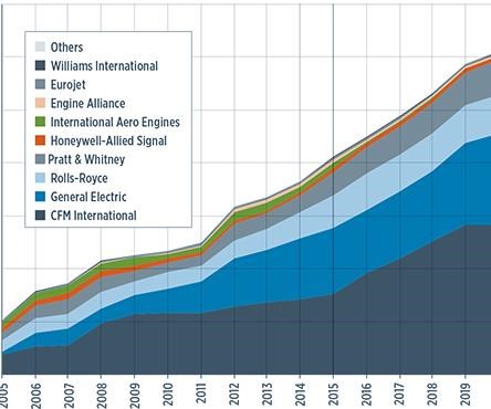
Based on figures compiled by Composites Forecasts and Consulting LLC (Mesa, AZ, US) in support of a recent production forecast for jets, turboprops and piston-powered planes during 2014-2023, we estimate that 67,710 turbofan-type jet engines will be needed to support expected global aircraft production (see Fig. 6). Nearly 47% of these engines will be destined for long-haul commercial transports. Business jets will consume the next largest number, accounting for about 37% of the market. Regional (short-haul) jets will make up about 5% of these deliveries. Military jets, including fighters and jet-powered unmanned aircraft, will require 11% — about 7,200 turbofans (plus some on-ground spares). Annual engine production has grown steadily since 2005 — engine deliveries totaled more than 5,800 units during 2014 — and is expected to peak in the 2018-2019 timeframe.
Engines and surrounding nacelles were expected to consume more than 16,320 MT of finished components, including those made of metals, composites and other materials, during 2013 alone. Of that total, composites accounted for an estimated 1,542 MT of flyaway weight — a significant increase over the roughly 454 MT delivered in 2005. Demand for composite aeroengine components will amount to nearly 1,680 MT in 2014, and we conservatively project growth to more than 2,765 MT per year by 2023 — based on known applications. Composites now represent about 9.5% of total engine flyaway weight. As the market matures during the years to come, this figure is expected to reach about 15%. And in the next 10 years, our study indicates that 23,587 MT of polymer composite structures will be manufactured in support of aircraft engine programs. This amounts to a US$16.2 billion market.
Nearly 85% of this engine-bound tonnage is destined for long-haul commercial aircraft. Regional jet programs are expected to account for about 3%. Business jets will consume another 8%, and military jets will need 4%.
Notably, nearly half of the projected total is earmarked for use on CFM International’s (Melun, France) CFM 56 and LEAP 1 families, which are used extensively to power the A320 and B737, and will soon be aboard the emerging MS-21 and C919 single-aisle transports. CFM International is a joint venture of GE (Evendale, OH, US) and SNECMA (Courcouronnes, France, a division of SAFRAN), so it should not be surprising that GE is the next largest consumer of composite engine components. Combined, CFM and GE will represent about 72 percent of total aeroengine composites demand. Over the next several years, however, Rolls-Royce’s (London, UK) Trent and Pratt & Whitney’s (East Hartford, CT, US) PurePower engine families are expected to account for a considerable portion of the 28% balance.
The majority of the aircraft engines reviewed for this study are produced by European and North American manufacturers. Our research indicates the latter currently control the lion’s share of total production, accounting for ~60% of the tonnage produced during 2014. France, through the SAFRAN group, holds close to a 30% share; Japan, Ireland, Italy, Spain, Belgium and Austria divide the majority of the remaining 10%.
Many engine manufacturers have significant in-house composites manufacturing capacity. GE Aircraft Engines, for example, has US facilities in Batesville, MS, Newark, DE, Baltimore, MD, Asheville, NC, and Ellisville, MS, as well as joint-venture subsidiaries. Rolls-Royce has reportedly purchased a large number of small fiber-placement machines for production of composite fan blades for upcoming engine platforms. Prominent tier suppliers in the engine composites segment include the following (with market shares noted):
• Albany Engineered Composites Inc. (Rochester, NH, US) 12.8%
• C-Fan (San Marcos, TX, US) 8.7%
• Nexcelle (Cincinnati, OH, US) 8.8%
• GKN Aerospace (Worcestershire, UK) 6.0%
• Aircelle (Gonfreville-l’Orcher, France) 3.9%
• FACC AG (Ried, Austria) 3.6%
Based on existing applications and current work shares, US manufacturers are poised to significantly increase their market shares during the forecast period. Anticipating that the US dollar will remain weak vs. major European and Asian currencies, we expect that North American manufacturers will control 70% of the market by 2023.
Processes and materials
Historically dominant, hand layup and autoclave cure of prepreg remains the most-used method for producing composite engine components. Filament winding also has a long history, but a much smaller role in aeroengines, as the method used to fabricate aramid fiber containment belts that surround fan cases.
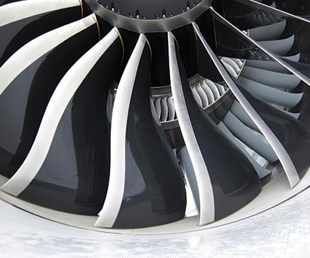
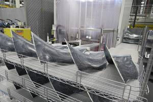
Like fabricators of other aircraft structures, engine builders have long sought to drive down manufacturing costs and maximize production output and efficiency. That quest has led the former to develop automated tape laying (ATL), automated fiber placement (AFP) and infusion processes for large primary structures. But the latter have been drawn to methods more readily applicable to relatively small but more complex engine parts. A case in point is CFM’s LEAP 1 (see photo, at left), expected to enter service later this decade. Individually placed, autoclave-cured prepreg plies have been replaced in its fan blades by 3D woven textile preforms processed by RTM. This strategy reduces composite part complexity and yields a dramatically shorter cure cycle, cutting the cost per unit of weight saved.
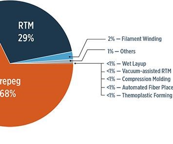
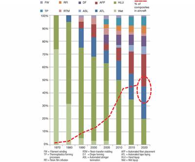
Fig. 8 illustrates that autoclave/prepreg and RTM processes (the latter accounting for nearly 30% of production) will continue to dominate the market over the forecast. Although RTM has proven to be the most adaptable processing alternative, multiaxial compression molding is emerging as a viable means to mold some smaller components, including fan platforms and, perhaps more interestingly, thrust reversers — an application historically dominated by suppliers based in Japan.
In terms of fiber reinforcements, our study found that glass, carbon and aramid fibers will continue to be incorporated into engine component laminates. Aramid, as noted, will reinforce fan containment cases. Glass fibers, currently, are used primarily in acoustic panels incorporated into nacelles. Standard-modulus carbon fibers will continue to reinforce some nacelle elements, but high-strength, standard-modulus and intermediate-modulus carbon fibers, together, will account for about 94% of the 12,474 MT of raw fiber destined for this market in the coming 10 years. High-performance, intermediate-modulus fibers alone will meet an estimated 83%, or 10,400 MT, of the forecasted fiber demand.
This study also looked at matrix resins. We estimate that 7,530 MT of resin materials will be required to support the prepreg, liquid RTM resins and molding compounds used to produce engine structures during the coming decade. Standard and toughened epoxies (121°C-cure and 176°C-cure) are expected to dominate, representing about 93% of the total, followed by bismaleimide and polyimide. Given the high-temperature applications in engines, this study also tracked the use of cyanate esters, phenolics, benzoxazines, phthalonitriles and thermoplastics, but only thermoplastics appeared in any sizable quantity, largely for engine brackets and for emerging thrust-reverser applications.
Future flight plan
As a result of continuing cost pressures on aircraft operators, the market for composite aeroengine components has nearly tripled since 2005. The durability and superior mechanical performance of carbon fiber composites, in particular, has been instrumental in enabling the production of high-bypass turbofans, through larger fan blades and lighter supporting and surrounding components in larger fan sections. Based on growing aircraft production rates, especially for commercial aircraft, our previously noted (and conservative) 2014 estimate of nearly 1,680 MT of composite engine components, worth more than US$1.1 billion, will grow, by 2023, to more than 2,665 MT of structures, valued at US$1.7 billion. Cumulatively, over the 2014-2023 forecast period, about 23,586 MT of engine composites will be fabricated.
That will provide considerable growth impetus for manufacturers of composite engine parts and their respective supply chains. Material suppliers will need to expand their raw materials output. After accounting for trim and waste in manufacturing processes, our study found that manufacturers will require nearly 33,113 MT of fiber and resin systems — primarily intermediate-modulus carbon fiber and toughened-epoxy resin systems. At base raw material prices, this represents more than US$1.4 billion in sales. After conversion into prepregs, infusible preforms, molding compounds and other intermediate product forms, the sales value will easily exceed US$2 billion.
On a final note, however, we should point out that the service-temperature range of polymer matrix composites effectively limits them to the engine’s front “cold” section. Although some polymer matrices can safely operate at temperatures greater than 177°C, the majority of engine weight is still concentrated in the engine’s “hot zone,” where low- and high-pressure turbine segments can see operating temperatures in excess of 1,315°C — well beyond the capabilities of even the most exotic polymers. The high cost and manufacturing difficulty associated with high-temperature metal alloys for these applications present a large target for future weight reduction efforts based on ceramics and ceramic-matrix composites. Now under development for use in CFM’s LEAP 1, in the turbine rotor shroud, these materials are likely to find application elsewhere in the next several years, including, for example, exhaust nozzles and bearings. Although the extent to which these newer materials might be applied across the broad spectrum of aircraft engine components has yet to be determined, there is considerable ground for engine-builder experimentation. In fact, potential opportunities for replacement of metals with ceramic matrix composites could be larger than those already claimed by polymer matrix composites.
Related Content
PEEK vs. PEKK vs. PAEK and continuous compression molding
Suppliers of thermoplastics and carbon fiber chime in regarding PEEK vs. PEKK, and now PAEK, as well as in-situ consolidation — the supply chain for thermoplastic tape composites continues to evolve.
Read MorePlant tour: Albany Engineered Composites, Rochester, N.H., U.S.
Efficient, high-quality, well-controlled composites manufacturing at volume is the mantra for this 3D weaving specialist.
Read MoreComposite resins price change report
CW’s running summary of resin price change announcements from major material suppliers that serve the composites manufacturing industry.
Read MoreBraskem demonstrates PP solutions using Weav3D composite lattice technology
Partnership combines Braskem’s polypropylene sheets with Weav3D Rebar for Plastics technology to address new structural, automotive applications requiring high-strength, lightweight material solutions.
Read MoreRead Next
Thermoplastics in Aerospace Composites Outlook, 2014-2023
Capable of volume production, thermoplastic composites will gain new market share in the aerospace industry.
Read MorePressure vessels for alternative fuels, 2014-2023
Lower fuel costs and escalating emissions standards are driving a 10 percent annual growth in alternative fuel pressure vessel sales.
Read MorePlant tour: Daher Shap’in TechCenter and composites production plant, Saint-Aignan-de-Grandlieu, France
Co-located R&D and production advance OOA thermosets, thermoplastics, welding, recycling and digital technologies for faster processing and certification of lighter, more sustainable composites.
Read More
