
Fastener pull-through strength test method
Mechanical fasteners have been used to join wood and metal plates for hundreds of years.
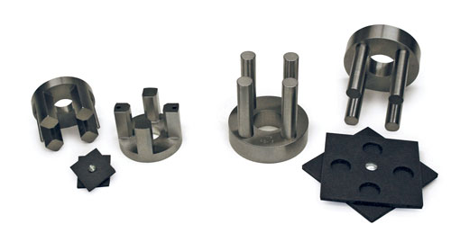
Fig. 2: Fixtures shown disassembled, with corresponding assembled test specimens. Source: Don Adams
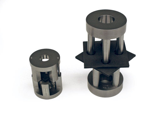
Fig. 1: Assembled MIL-STD-1312-8 test fixture (left); ASTM D 7332 test fixture (right). Source: Don Adams
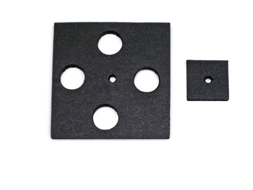
Fig. 3: MIL-STD-1312-8 specimen plate (left); ASTM D 7332 specimen plate (right). Source: Don Adams

Dr. Donald F. Adams is the president of Wyoming Test Fixtures Inc. (Salt Lake City, Utah). He holds a BS and an MS in mechanical engineering from, respectively, the University of Illinois and the University of Southern California, and a Ph.D in theoretical and applied mechanics from the University of Illinois. Following a total of 12 years with Northrop Aircraft Corp., the Aeronutronic Div. of Ford Motor Co. and the RAND Corp., he joined the University of Wyoming, directing its Composite Materials Research Group for 27 years before retiring from that post in 1999. Dr. Adams continues to write, teach and serve with numerous industry groups, including the test methods committees of ASTM and the Composite Materials Handbook 17 (CMH-17).


Mechanical fasteners have been used to join wood and metal plates for hundreds of years. Because mechanical fastening of composite material plates is a much more recent development, most of the standard test methods that evolved during the past century for testing fastened-joint strength were developed specifically for joints between metal plates.
One of the several ways a mechanical joint can fail is when the fastener is subjected to axial tension, that is, the plates are pulled apart by an applied load. In this case, either the fastener breaks or the head of the fastener is pulled through one of the plates. For metals, the former is usually of greatest concern. But for composites it is often the latter because most fasteners today are high-strength metals (typically, steel alloys). The composite plates are usually relatively thin and, because they are designed to have high in-plane strength, are not nearly as strong in the through-the-thickness direction.


In practice, the typical mechanical joint is made with many fasteners that are arranged in a specific pattern, and a detailed stress analysis is required to determine that portion of the total load carried by each fastener. However, it is the load-carrying capacity of the most highly stressed fastener that becomes the critical parameter in the joint design. For that reason, test methods typically focus on a specimen joined by a single fastener. The fastener may be a screw, bolt or rivet, but the general problem is the same.
One of the oldest test standards, still in use today, was developed to determine the strength of the fastener itself rather than the plates it joins together. As a military standard, designated as MIL-STD-1312-8,1 it was intended for use with metal plates. One of several fastener test method standards included in MIL-STD-1312, it was revised in 1983 (Revision A), and then, in 1997, it was re-issued as National Aerospace Standard NASM 1312-8 by the Aerospace Industries Association of America Inc. (Arlington, Va.).2 This standard (in the original and re-issued versions) contains two specimen configurations and their corresponding test fixtures (see Fig. 1). Both are used today to test the pull-through strength of composite plates. The specimen and fixture on the right in Fig. 1 was subsequently adopted for use in Procedure A in ASTM Standard D 7332,3 first published in 2007. Although the specimen and fixture on the left were not included in the new ASTM standard, they are still in common use and, for purposes of this discussion, will be referred to here as the MIL-STD configuration.
Both configurations are primarily intended for screening purposes. However, ASTM Standard D 7332 also includes a Procedure B, which is configuration-dependent and intended for generating design data. That is, the specimen size and fixture geometry are not fixed but instead are to be configured for the specific design application. Procedure B will be discussed in a future column.
The two fixtures in Fig. 1 are shown disassembled in Fig. 2 along with their corresponding test specimens. Note that each test specimen consists of two plates fastened together at their centers, with one plate rotated 45° in relation to the other so that all eight corners are exposed. An individual plate from each specimen is shown in Fig. 3.
The individual plates that make up the MIL-STD specimen are 38 mm/1.50 inches square. When the specimen is installed in its fixture, the four corners of the upper plate rest on the four posts that protrude from the fixture base. Then the top portion of the fixture is placed in position, its four posts resting on the four corners of the lower plate. Guide pins ensure proper relative positioning of the two halves of the fixture. As a downward force is applied to the top of the fixture assembly, the two plates are pushed apart, inducing a tensile force in the fastener. The desired failure is pull-through of the fastener as one or both plates fail around the fastener hole. The test is considered to be invalid if the fastener fails or a plate fails away from the fastener hole.
The individual plates that make up the ASTM specimen are 108 mm/4.25 inches square, with four 19-mm/0.75-inch diameter holes, located 90° apart on a 69-mm/2.75-inch diameter circle, at the midsides of the plate, as in Fig. 3. When the assembled specimen is placed on the four 18-mm/0.70-inch diameter circular posts of the ASTM fixture base, the posts pass through the holes in the lower plate and contact the upper plate near each corner. Correspondingly, the four posts of the top portion of the fixture pass through the holes in the top plate and rest near the corners of the lower plate.
Each fixture has advantages and disadvantages. In the ASTM design, the loading is effectively the same as that for the MIL-STD fixture, but the clearance holes allow the forces to be applied farther in from the plate corners. This can be advantageous when there is a risk that plate corners might fail prior to fastener pull-through. Although the ASTM fixture does not have guide pins that align the two halves of the fixture, aligning them visually is not difficult. However, the standard-sized ASTM specimen consumes considerably more material than the MIL-STD specimen because its plate area is more than eight times larger (Fig. 3). Of course, either standard could be modified to make the specimen sizes equal. However, if the MIL-STD specimen is increased in size, the plate deflections under load will increase. This is undesirable because it alters the joint geometry and might not be representative of service conditions. Presumably, this is why the MIL-STD plates are kept small. Further, the holes that must be machined in each ASTM specimen (four in each plate) add significantly to the preparation cost — definitely a negative factor.
As the preceding discussion suggests, the smaller and less expensive standard MIL-STD specimen and its fixture are more commonly used to test fastened composite plates, and I would recommend trying them first. That said, I believe the larger, drilled specimen and fixture is likely, despite its additional expense, to increase in popularity now that it is specified in ASTM Standard D 7332. If premature corner failures occur with the former, it might be necessary to switch to the latter.
References
1 MIL-STD-1312-8A, “Fastener Test Methods, Method 8, Tensile Strength,” Naval Air Engineering Center (Lakehurst, N.J.), 1983.2NASM 1312-8, “Fastener Test Methods, Method 8, Tensile Strength,” Aerospace Industries Assn. (Washington, D.C.), August 1997.
3ASTM D 7332-07, “Measuring the Fastener Pull-Through Resistance of a Fiber-Reinforced Polymer Matrix Composite,” ASTM International (W. Conshohocken, Pa.), April 2007.


Related Content

Notched testing of sandwich composites: The sandwich open-hole compression test
A new ASTM-standardized open-hole compression test method seeks to determine the notch sensitivity of sandwich composites.
Read More
Numerical tool with mean stress correction demonstrated for fatigue life estimation of thermoplastic composites
To aid design of fatigue-resistant structures, Econ Engineering has developed an algorithm to evaluate ply-based cyclic stiffness degradation combined with an FE failure check, validated for a CF/PAEK pressure vessel.
Read More
Measuring ply-wise deformation during consolidation using embedded sensors
Strip-type shape sensor method claims real-time measurement of ply-wise deformation.
Read More
Composite prepreg tack testing
A recently standardized prepreg tack test method has been developed for use in material selection, quality control and adjusting cure process parameters for automated layup processes.
Read MoreRead Next

Composites test method globalization and harmonization
In my previous column, I discussed the need for standardization of test methods and the progress that has been made in recent years (see “Related Content,” at left). However, we know from that column, and many preceding it, that when we attempt to determine material properties, there is often more than one
Read More
Single-fastener, double-shear laminate bearing strength by tensile testing
Dr. Don Adams (Wyoming Test Fixtures Inc., Salt Lake City, Utah) discusses a laminate bearing strength test using double-shear loading of a single fastener.
Read More
Why standardize composites test protocols?
Every column I write for HPC eventually refers to “standard” test methods. But why are standards written? What groups promote these standards, and who actually writes them? Most importantly, why do the rest of us need to follow their standards, and what if we don’t? To answer the first question, we must step back into
Read More