Getting part dimensions right in composites molding
Guest columnists Dr. Göran Fernlund (left) and Dr. Anoush Poursartip (right) of Convergent Manufacturing Technologies (Vancouver, BC, Canada) argue that today's CAD design and process simulation software can construct a "multi-physic process model" accurate enough for reliable dimensional management.
Composite parts never have the same dimensions as the tool on which they are processed. Mechanisms such as tool dimensional change during heat up and residual stress buildup within the part during cure/solidification and cool-down are the cause. Many are familiar with results such as “springback,” which is the closing of angles due to strain anisotropy1. This is true for all composite materials and processes — only the mechanisms differ between them and then, only slightly. Dimensional change is a problem if its magnitude is greater than the part’s dimensional tolerance requirements.
Aerospace structure tolerances can be as tight as ±0.25 mm, and meeting tolerances this narrow can be difficult without a good dimensional-management strategy.
Anyone who has baked a cake knows that how it turns out depends not only on the ingredients in the batter but also the type of pan and oven, the pan’s location in the oven, the baking temperature and time, and the cool down and removal from the pan. The same is true for composites processing. Dimensional management is a systems level problem, and many parameters affect cured-part dimensions. The systems parameters that affect dimensional change (and any other outcome in a composites process) can be divided into three broad groups related to the part, the tooling and the process2:
- Part: Geometry, material behavior and layup
- Tooling: Geometry, material behavior
- Process: Temperature, pressure, time and heat transfer
These factors all interact to determine the outcome.
If a tool is machined to the composite part’s nominal engineering dimensions, dimensional measurements on multiple parts pulled from that tool will generally show a mean deviation from nominal and some variability around that mean. If the total deviation from nominal is less than the dimensional tolerances, dimensional conformance is achieved and no further action is required. If not, the part, tooling and/or process have to be modified to achieve dimensional conformance. This can be a costly and time-consuming iterative process, because it is difficult to anticipate the effect of system parameter changes if there is no predictive model.
It is increasingly unacceptable to depend on trial and error to achieve dimensional conformance, especially after the tool is made and full-scale part production has begun. Alternatives include depending on experience, consulting expert opinion and performing tests. The first two often fall short if the part and process is complex or deviates from the previous experience base. Test data are often of limited use because cured dimensions depend on part, tooling and process, which can make scaling of results from small test coupons to the full-sized part/process misleading and, thus, risky. A more effective option, particularly for large, complex structures, is computer simulation, where a physics-based model is generated and links systems parameters related to the part, tooling and process to the process outcomes — in this case, dimensional change.
To accurately predict that change, the model must include a high-fidelity description of the part, including its geometry, the layup and details of the composite material’s behavior as its properties evolve during the cure/consolidation cycle. Also necessary is a good description of the tooling, including its geometry and its thermo-physical properties. Finally, the model must capture the process: temperature and pressure application over time, and heat transfer to the part and tool3. This type of multi-physics process model is, internally, fairly complex but can be relatively easy to set up and run if the right software-based solution package is selected.
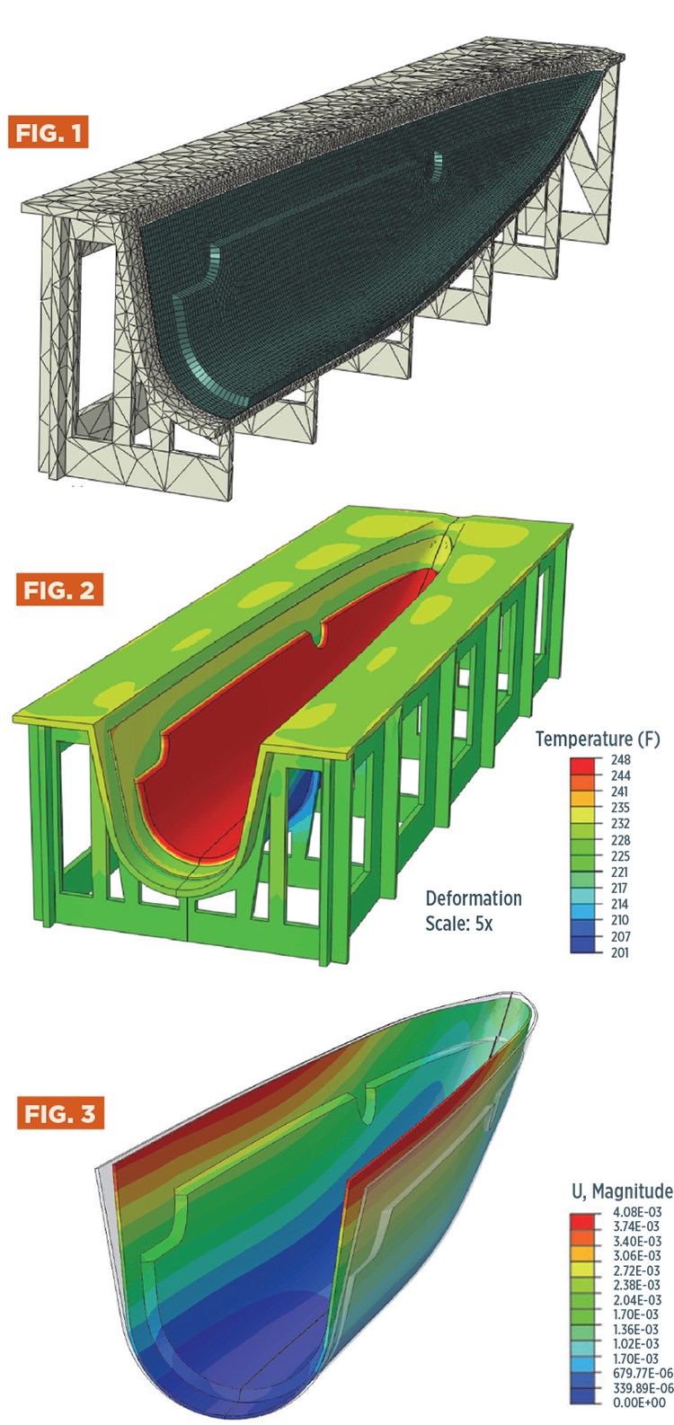
There are several software tools on the market that can be used for design and simulation. For the purposes of our example, we used Dassault Systèmes’ CATIA and ABAQUS design and simulation software with Convergent Manufacturing Technologies’ COMPRO process simulation software (Fig. 1, at left). Fig. 2 shows the predicted temperature gradient during heat ramp-up. When a process model is created for the part, tool and process of interest, it can be used to predict the expected mean dimensional change (Fig. 3) and to identify parameters that drive process variability. Often, the most effective way to address the part’s mean dimensional change is by geometric compensation of the tool surface because it can be done without changing laminate or process parameters. Using the COMPRO/CATIA/ABAQUS solution set, geometric compensation of the tool can be performed automatically by transferring the calculated dimensional change back to the CATIA design environment and morphing the tool surface so that dimensional conformance is achieved. Altering the layup sequence and/or modifying the cure cycle are alternatives that can be developed and evaluated in the same simulation environment.
Once the system parameters have been adjusted to give a mean dimensional outcome that matches the nominal dimensions, the model can be used to identify and set bounds on the allowed variability of systems parameters, such that the dimensional variability of the part is within dimensional tolerances.
The technology and methodology presented here is routinely employed by large aerospace OEMs, and it is clear we have reached a tipping point: Powerful and effective process simulation tools and inexpensive, fast computational power are converging. Composites fabrication need no longer be treated as an art and should leave the domain of empiricism. Processing can be approached with the same analytical mindset and design and simulation tool sets as any other aspect of engineering. This is critical if we are to build large, complex composite structures that can compete with metal structures. The era of simulation-supported, knowledge-based composites manufacturing is here, and there is no turning back if we want to remain competitive.
References
1 Nelson, R. H., & Cairns, D. S. (1989). “Prediction of dimensional changes in composite laminates during cure,” Tomorrow’s Materials: Today, 34, 2397-2410.
2 Johnston, A., Vaziri, R., & Poursartip, A. (2001). “A plane strain model for process-induced deformation of laminated composite structures.” Journal of Composite Materials, 35(16), 1435-1469.
3 Fernlund, G., Floyd, A., Shewfelt, M. & Hudek, M. (September 2007). “Process analysis and tool compensation for a complex composite panel,” Proceedings of the 22nd American Society for Composites Technical Conference (Seattle, WA, US).
Related Content
Plant tour: Airtech International, Springfield, Tenn., U.S.
Fifty years of supplying materials for composites manufacturing includes custom fabrication and now aims to advance 3D-printed tooling, parts and new resins.
Read MoreBladder-assisted compression molding derivative produces complex, autoclave-quality automotive parts
HP Composites’ AirPower technology enables high-rate CFRP roof production with 50% energy savings for the Maserati MC20.
Read More3D-printed CFRP tools for serial production of composite landing flaps
GKN Aerospace Munich and CEAD develop printed tooling with short and continuous fiber that reduces cost and increases sustainability for composites production.
Read MoreTPI, UMaine, ORNL to leverage world’s largest polymer 3D printer for wind turbine tooling
Ingersoll Masterprint LFAM printer will be used to produce and demonstrate 100% recyclable tooling that could cut large composite blade development cycles and tooling costs by as much as 50%.
Read MoreRead Next
Plant tour: A&P, Cincinnati, OH
A&P has made a name for itself as a braider, but the depth and breadth of its technical aptitude comes into sharp focus with a peek behind usually closed doors.
Read MoreVIDEO: High-rate composites production for aerospace
Westlake Epoxy’s process on display at CAMX 2024 reduces cycle time from hours to just 15 minutes.
Read MoreModeling and characterization of crushable composite structures
How the predictive tool “CZone” is applied to simulate the axial crushing response of composites, providing valuable insights into their use for motorsport applications.
Read More
