Laser projection systems improve composite ply placement
Lighter, more intelligent and increasingly versatile laser systems light the way to accurate and efficient ply placement.
When laser projection systems first replaced physical templates in aerospace composite layup in the 1990s, the result was nothing short of revolutionary. "The customer documented that lasers eliminated 80 percent of the fabrication time," says Scott Blake, president of Assembly Guidance Systems (Chelmsford, Mass., U.S.A.), of one of his earliest customers' experience with his company's laser placement equipment.
Previously, the customer had layed up its 28-ft long helicopter rotor blades in the traditional time-consuming process, using three 9-ft long fiberglass templates for each composite ply. Each template had to be lifted by two people, and then the three had to be bolted together, pinned into the tool, scribed for the outline and then removed before the ply could be placed. The process had to be repeated for each successive ply.
Assembly Guidance replaced the physical templating system with one of the first commercial laser systems, which simply projected ply patterns onto the tool.
The system's effect on the company's operations turned out to be dramatic: Aside from the obvious labor savings, design changes could be turned around in a matter of days rather than the weeks it previously required because the physical templates had to be modified or replaced. (Today, due to some of the advances described below, the turnaround occurs in about an hour.) Almost from inception, the systems were used for inspection (e.g., to validate placement of fasteners) and, because they are computer-based, documentation, as well. And the company was able to reclaim for other uses the large area of the manufacturing facility previously devoted to template storage.
While laser placement produced a giant step forward in layup efficiencies in the early 1990s (documented in HPC September/October 1994, p. 32), the decade-and-a-half since their introduction has been marked by significant strides in the technology that have expanded their application both inside and outside the aerospace arena.
Shedding light on system essentials
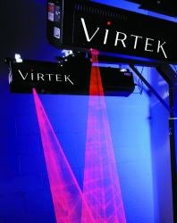
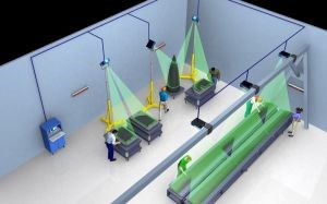
The basic laser projection system, then and now, consists of a projector mounted above the layup area, a computer controller and a set of retroreflective alignment pins, which are positioned on the tool edges and used as reference points to establish the tool's exact position in three-dimensional space. List prices for a full turnkey system, with two projectors, equipment stands and training, range from about $85,000 to $100,000 (USD), depending on the manufacturer. To use the system, the fabricator first positions the layup tool under the projector. The projection system self aligns by scanning the tooling surface with light, which is reflected by the pins back along the same optical path to a photodetector, which allows the system to "read" the position.
Once the projection system verifies tool position, it can accurately project the outline of each ply to be layed up. The system software stores imported computer-aided design (CAD) outlines of layup plies and adjusts the size and shape of the projected outline to account for the tool's three-dimensional contours. The heart of the projector is a laser, which produces a beam of light focused to a point. A set of mirrors and galvanometers in the projector redirect the beam so that it travels the path of the ply outline at a speed great enough to appear to the layup technician as a solid line. After each ply is placed in the tool, the technician simply pushes a button to advance to the next pattern.
Lasers used in ply placement have changed dramatically from large, hot, gas-fired systems that projected red beams in the early '90s to cool running diodes the size of a finger that project a more visible green light. Early projectors weighed upwards of 27 kg/60 lb, making mounting and servicing somewhat inconvenient. Early laser sources were not always reliable either, and limitations on galvanometer speed created a flickering effect the farther the projector was from the tool, limiting the working envelope to about 10 ft square. Furthermore, software that imported the CAD data to produce the correct projection pattern was clumsy and far from transparent, and user interfaces were more complex than desired.
Common benefits
The laser systems of 2004 have advanced significantly in each of these areas, and added other features to enhance their usefulness. Assembly Guidance, Virtek Vision International Inc. (Waterloo, Ontario, Canada) and Laser Projection Technologies (LPT, Londonderry, N.H., U.S.A.) each have helped advance the state of the art in laser projection for composites applications, an advance that Bob Jackson, Virtek product line manager, describes as a "continuous improvement program - we're always looking at how to evolve the product."
With the advent of green diode lasers, standard projector weight has decreased to a range of 10 to 20 kg (22 to 45 lb). Smaller, lightweight projectors for use in confined spaces have been developed by both LPT and Assembly Guidance. The LPT model weighs only 2 kg/4.5 lb and measures 300 mm long, 130 mm wide and 100 mm deep (12 inches by 5 inches by 4 inches), while Assembly Guidance offers a 3.5-kg/8-lb model measuring 200 mm by 100 mm by 100 mm (8 inches by 4 inches by 4 inches).
Optics also has improved. All three companies report accuracies today within ±0.38 mm/0.015 inch. While accuracy still decreases as the distance from projector to tool increases, the practical working envelope for less demanding applications can extend to 12m/40 ft or more without increasing the laser power to unsafe levels. Laser power output is regulated for worker safety. LPT and Virtek laser placement systems use CDRH Class IIIa or IEC Class IIIR visible laser diode devices and Assembly Guidance systems are Class II. (CDRH is the Center for Devices and Radiological Health, an agency of the U.S. Food and Drug Admin. (FDA). IEC is the International Eletrotechnical Commission.) No protective eyewear or work area enclosure is required for these classes of systems.
The newer systems are smarter, on the strength of significant developments in the technologies and software that support the lasers. For instance, the auto-alignment features that locate the layup tools beneath the laser projectors have become more forgiving. With earlier systems, the tool had to be manually located beneath the projector with some precision, because each retroreflective pin or target had to be placed within a roughly 50-mm/2-inch square window for the laser system to be able to find the pins and align. Today, the window is 150 mm/6 inches or wider. In addition, while the tool is being positioned, today's laser placement systems can project an outline of the placement window for each alignment pin or project the footprint of the entire tool - and can even alert technicians when a nearly symmetrically shaped tool needs to be rotated 180°. "The speed and reliability with which this alignment process can be repeated continues to be an important consideration in the overall productivity of laser projection systems," Virtek's Jackson notes.
The three companies also have developed relatively transparent software interfaces to popular CAD and flatpattern programs. The spread of VISTAGY's (Waltham, Mass., U.S.A.) FiberSIM in the mid-1990s prompted laser placement providers to write appropriate import software for this package, followed by good interfaces with CATIA Covers, from Dassault Systemes (Woodland Hills, Calif., U.S.A.). Additionally, laser projector manufacturers have developed (or are considering development of) interfaces to common CAD file formats, such as IGES and DXF. These direct links to CAD files are expected to make laser systems more attractive to composites manufacturers that do not use FiberSIM or CATIA Covers.
"Nonaerospace companies are using a whole variety [of CAD systems] other than CATIA - Unigraphics, AutoCAD, ProEngineer to name a few," explains LPT's Joe DiVito, director/business development. LPT has teamed with Magestic Systems (Old Tappan, N.J., U.S.A.) to make laser projection more accessible. With Magestic's TruLASER VIEW CAD software and an LPT system, he maintains, "You don't have to invest in other software to access the CAD files."
Out of the cleanroom
In addition to the innovations common to all systems, composites manufacturers that have recently invested in new laser placement systems, for the first time or to replace older models, also mention a variety of capabilities that prompted their selection of specific systems.
When asked what new features of LPT systems are most advantageous to operations at the Boeing Phantom Works plant (St. Louis, Mo., U.S.A.), structural design engineer Michael Hayes says, without hesitation, the sealed projector installed last year. "It tolerates a shop floor environment," he explains.
Historically, laser placement systems have been designed for cleanroom environments, leaving the air-cooled optical components vulnerable to airborne contaminants if used elsewhere. Designed to extend the breadth of applications for laser placement systems, LPT's sealed projector incorporates a patented internal cooling matrix, which takes in external air and passes it through the projector's cooling system without exposing the optics to the air.
Phantom Works owns 15 LPT systems, 12 of which are used on its shop floor in a variety of R&D projects intended to expedite assembly of the company's aircraft. Several apply laser-projected images to noncomposite structures, including fastener positioning on the F-15 Eagle, and inspection of fastener positions on the C-17 Globemaster cargo aircraft's cargo ramp and cargo door assemblies. The laser indicates the correct position for the fastener, eliminating hand layout of the holes and ensuring that the fastener is positioned in the middle of the stringer or other understructure.
Phantom Works also applies LPT systems to incoming quality control on composite skins for the F/A 18 E/F SuperHornet, which are fabricated by an outside vendor. If a skin comes in with a poor fit, the laser system helps technicians determine where the skin is out of spec. Further, laser projection is being tested for its potential to verify trim lines on the composite skins fabricated by Northwest Composites (Marysville, Wash., U.S.A.) for the C-17 aircraft's landing gear pod. Phantom Works currently does the final trimming, but a project goal is to develop the data set that will eventually enable Northwest Composites to trim the part prior to shipment.
Hayes also cites the LPT system's versatility. "Once you hang it above your assembly, you can do many things at one spot," he says. Although he uses standard 20-kg/45-lb projectors, Hayes highlights ease of mobility. Phantom Works assembles the C-17's massive cargo ramp in a three-story tooling jig. The jig's design prevents him from locating the projector very far from the surface to be inspected, so Hayes repositions the projector successively over six different windows, each about 3.5m/12 ft square. Although he must move the projector five times, he reports, "It takes only ten minutes to break it down and set it back up in the new position." Should this operation move into full production, Phantom Works could speed the process by dedicating more projectors to this application in a "hard" setup. LPT, like the other laser placement system providers, has developed software that enables multiple projectors to operate from a single controller on the same project. The software "stitches" the projections from the lasers together to ensure an accurate, seamless outline.
LPT's sealed projector also is in service in the marine industry. Sea Ray Boats (Knoxville, Tenn., U.S.A.), for example, uses an LPT system to locate core details and wood bracing that is eventually covered with chopped fiberglass. The dust and debris from chopped glass as well as nearby metalworking operations is a far cry from the cleanroom environments used for hand layup of aerospace composites.
Automotive composites manufacturer Sparta Composites (San Diego, Calif., U.S.A.) uses an LPT system to place unidirectional carbon/epoxy prepreg plies for the inner structure of the rear engine deck lid on the new Ford GT sports car. (See "Parts Consolidation a Key to Lower Cost," HPC January 2004, p. 16). The inner structure's complex contours and fine details demanded a very high number of patterns. Top these requirements off with the need to produce the parts at limited-run automotive production rates (nine per day for a component that, in aerospace operations, might be fabricated at a rate of one every three days), and the necessity of laser placement technology is obvious. "We couldn't have layed up this part without this system," says Sparta Composites' Mike Vairo, division manager, composites product manufacturing.Using four LPT systems, he maintains, "We can meet Ford's required production rate for the GT deck lid."
Projection for cutting and nesting
Recent software innovations have expanded the laser placement systems of all three companies to ply cutting rooms,where laser projectors indicate the sequence to pick up and kit prepreg patterns from the CNC cutting tables. Further software developments permit the laser controller to import data from commonly used nesting programs. For example,Sparta Composites uses one of its LPT systems in conjunction with a CNC cutting system from Autometrix Precision Cutting Systems (Grass Valley, Calif., U.S.A.). With as many as 100 patterns cut from a single swath of prepreg,the LPT system is indispensable in saving time and reducing errors in the kitting process.
LPT also worked with Sparta Composites on a software issue peculiar to its cutting operation. "The main thing LPT did," explains chief engineer Joe Cook, "was to give us a way of telling its system where the plies were on the table -the local '0,0.'" LPT's willingness to work on its software was a selling point for Sparta Composites, reports program engineer J.T. Lyons.
The other three LPT systems are all used for layup templating, for which the Sparta Composites engineers mentioned a number of beneficial features. The biggest draw to LPT, though, was cost. LPT has gained a reputation as a provider of more economical laser projection systems. This reputation was born out for Sparta Composites, Lyons reports. "We got a little more bang for the buck," he says,noting that LPT provided four projectors for a price the company expected to pay for three.
Broadening system functionality
Assembly Guidance features two distinctive capabilities in its laser systems: multitasking controllers that simultaneously run jobs on multiple, independent tools, and Automatic Ply Verification (APV), an in-process quality monitoring system.Multitasking controllers have streamlined operations at Sikorsky Aircraft Corp. (Stratford, Conn., U.S.A.) during fabrication of the RAH-66 Comanche helicopter. Sikorsky's composites layup cleanroom houses some 300 tools, and a dozen layups may be under way at any given time. Assembly Guidance provided 28 projectors, which require only eight controllers because each controller supports up to eight projectors and can run as many as six entirely independent jobs simultaneously.
To illustrate the function, Sikorsky project engineer Al Trudeau notes that the multitasking controller, for example,might project templates onto one tool using three projectors configured in a line, while it also projects templates onto another tool with four projectors configured in a square.One controller aligns each set of projectors independently by establishing different coordinate systems for each tool.The controller also can reassign projectors according to the demands of the particular projects under way. Trudeau reports that the cleanroom might concurrently use four or five different geometric configurations of the projectors.
APV is a controller-based feature that electronically inspects some or all of the patterns in a particular layup. Typically at Sikorsky, APV randomly selects about 10 percent of the patterns. After the operator has laid in one of these plies and before advancing to the next pattern, the Assembly Guidance system prompts the operator to place a digital camera mounted in a small bracket on the layup. The base of the bracket sits on the surface while the bracket holds the camera a few inches above the ply to be inspected. By wireless transmission, the controller acquires a digital image of the ply, which the system uses to automatically determine if fiber orientation, material type and ply position are correct. The controller captures the result and formulates a report, which is stored and can be printed and added to the document "traveler" that goes with the part.
Customer response
Virtek, another pioneering company in laser placement technology, has developed features of its systems specifically in response to customer needs. Discussing the recent completion of a $1.7 million (Canadian) installation at Lockheed Martin Aeronautics Co. (Fort Worth, Texas, U.S.A.), for example, Virtek president and CEO Bob Sandness comments, "Lockheed Martin purchased Virtek's first laser templating and positioning system for the layup of composite plies in 1992 and has provided input into the LaserEdge product's development ever since." This latest installation will be used in Lockheed Martin's fabrication of composite parts for the F-35 Joint Strike Fighter and F/A-22 Raptor fighter jets. Virtek's Jackson adds, "We don't customize, but try to incorporate the benefits that many people have been looking for, so that each can take advantage of them."
Virtek's strongest emphasis is on reliability, both in technology and service. "We probably shoot as hard a project as anyone in the business," declares Virtek customer Larry Tener, senior equipment engineer at the Raytheon Composite Center of Excellence (Wichita, Kan., U.S.A.). "We turn [our Virtek systems] on everyday, and they work."
Raytheon bought seven Virtek projectors this year, bringing the total currently in use at the company to 18. Several of these are employed with automated tow-placement mandrels, to guide hand layup work performed in conjunction with the automated layup. The Virtek systems are able to accurately align and project ply outlines on a round "water bottle" shaped rotating mandrel, Tener points out.
Furthermore, startup with Virtek projectors is highly reliable, says Tener. "We get a new Virtek in, fire it up, let it get stable, and within 45 minutes we've certified it and it's ready to go into our production projects - without help from Virtek factory assistance," he emphasizes.
Virtek's robust systems typically are higher priced than competitors, Tener notes, but Raytheon has justified that cost with the quick startup and low downtime, as well as excellent customer service when needed. He concludes, "They're not the cheapest in the business, but I can count on them to come up every day and shoot light where they are told to."
"It's hard to be innovative over the long term when you try to play the low-price game," says Virtek's Jackson, acknowledging his product's premium price. "We don't play that game." Jackson and Sandness both highlight Virtek's goal of providing 'best value,' which they define as a combination of quality, affordability and other development and production criteria.
Attention to the simple things
Interestingly, of the features cited as particularly helpful to the end-user, several customers put great emphasis on convenience enhancements. For example, the Assembly Guidance system used in layup operations at Lockheed Martin Aeronautics (Fort Worth, Texas, U.S.A.) employs an easily visible LED display to post the next pattern to be laid up. "Instead of going to the computer screen, you can verify what you're doing from a considerable distance," notes Todd Ashton, Lockheed Martin senior research engineer. He also appreciates the system's remote control. "You can do everything - index through a ply stack, change tools, pick out registration targets, and so on."
Keeping the revolution going
Each laser placement company has attracted a loyal customer base through the unique aspects of its individual product offerings. Not surprisingly, all three underscore the importance of customer service and follow up. As system innovations continue to come online, demonstrating the utility of laser technologies in broader applications within composites manufacturing operations, their makers fully expect this key technology to achieve greater market penetration.
Related Content
Improving carbon fiber SMC simulation for aerospace parts
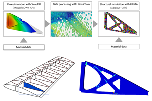
Simutence and Engenuity demonstrate a virtual process chain enabling evaluation of process-induced fiber orientations for improved structural simulation and failure load prediction of a composite wing rib.
Read MoreActive core molding: A new way to make composite parts
Koridion expandable material is combined with induction-heated molds to make high-quality, complex-shaped parts in minutes with 40% less material and 90% less energy, unlocking new possibilities in design and production.
Read MoreOptimizing a thermoplastic composite helicopter door hinge
9T Labs used Additive Fusion Technology to iterate CFRTP designs, fully exploit continuous fiber printing and outperform stainless steel and black metal designs in failure load and weight.
Read MoreATLAM combines composite tape laying, large-scale thermoplastic 3D printing in one printhead
CEAD, GKN Aerospace Deutschland and TU Munich enable additive manufacturing of large composite tools and parts with low CTE and high mechanical properties.
Read MoreRead Next
Plant tour: Daher Shap’in TechCenter and composites production plant, Saint-Aignan-de-Grandlieu, France
Co-located R&D and production advance OOA thermosets, thermoplastics, welding, recycling and digital technologies for faster processing and certification of lighter, more sustainable composites.
Read MoreAll-recycled, needle-punched nonwoven CFRP slashes carbon footprint of Formula 2 seat
Dallara and Tenowo collaborate to produce a race-ready Formula 2 seat using recycled carbon fiber, reducing CO2 emissions by 97.5% compared to virgin materials.
Read More“Structured air” TPS safeguards composite structures
Powered by an 85% air/15% pure polyimide aerogel, Blueshift’s novel material system protects structures during transient thermal events from -200°C to beyond 2400°C for rockets, battery boxes and more.
Read More







.jpg;maxWidth=300;quality=90)


