Lightweighting a heavyweight
Process combination produces significantly lighter overhead storage bins for big-rig sleeper cabs.
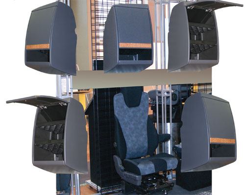
For trailer-truck operators in the long-distance commercial transport market, every pound saved in vehicle weight translates to higher payload capacity or better fuel efficiency — a key point as diesel prices, once much lower than gasoline prices, now track with the latter (~$3/gal in the U.S.). That fact prompted a major truck OEM to approach heavy-duty truck component producer Commercial Vehicle Group Inc. (CVG, New Albany, Ohio) for a redesign of its overhead storage cabinets. Used in its “sleeper cab” models (those that accommodate sleeping quarters), the airline-style bins are part of a trend toward more functional and inviting “sleepers” for long-haul truck-driving teams.
“We replaced an injection-molded plastic and metal assembly with a composite design and achieved significant part consolidation and weight savings,” recalls Pat McAllister, engineering manager at CVG’s Concord, N.C., facility, one of the company’s 20 Global Truck production plants. “We’ve designed in strength in certain areas, and tailored the load paths, so that other areas don’t need as much strength or stiffness, saving overall material cost,” says CVG’s R&D lead engineer for development Keith Overton. The key to project success, however, was the decision to manufacture the individual components that make up the cabinet assembly via a combination of typical automotive part processes, each method contributing key characteristics that optimized the particular part’s intended performance.
A trio of processes
At the onset of the project, CVG faced the challenge of balancing three often incompatible imperatives. “Our primary goals were less weight while still maintaining adequate performance, and meeting our own cost target,” notes Overton. CVG’s industrial design group took the lead: “We went from our customer’s rough concept sketch to detailed CAD models for the part as well as for the tooling,” says McAllister. The group’s working three-dimensional CAD models were tweaked to meet styling, dimensional and functional requirements. Prototypes were constructed and tested, via finite element analysis and physical tests, to confirm design assumptions.
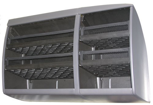
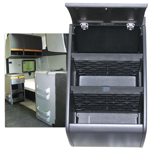
The result of the design process was a multipiece cabinet approximately 30 inches/762 mm high and 18 inches/457 mm deep, in two configurations: a “single” cabinet at 20 inches/508 mm wide, and a “double” at 45 inches/1,143 mm wide, to give the OEM customer options for various sleeper cab configurations. Further, a single and a double could also be combined into one “long” cabinet version, notes Overton.
Proceeding hand-in-hand with part design was evaluation of the best manufacturing approach for the various pieces or components that make up the cabinet assembly. CVG selected three rapid and cost-effective processes that could best meet the design goals for the individual parts. According to Overton, the cabinet’s primary load-bearing elements, the two inner shelves, are injection molded using a glass fiber-filled, impact-modified polypropylene from a proprietary supplier. The cabinet enclosure, which consists of two end panels, a one-piece back/top panel, a bottom shelf and optional doors, are made using two separate reaction injection molding (RIM) methods. The first, a company-developed and proprietary method termed T-RIM, is used for the cabinet’s bottom shelf. The material is a two-part, thermoset urethane foam system reinforced with a proprietary “organic” filler. The second RIM method is used for the remainder of the cabinet enclosure elements. Known as Improved Vinyl Clad Rigid, or IVCR, it uses the same urethane foam resin system, but without added reinforcement. Both RIM processes incorporate cosmetic vinyl outer skins and comolded steel inserts to accommodate fasteners during cabinet assembly.
McAllister points out that the tools were designed in tandem with the parts, with care taken to avoid tight radii or deep draws, and provide ways to accommodate the inserts. CVG worked with its tooling fabricator in an iterative manner, to ensure no surprises once manufacturing got underway. The injection molding tools for the two shelf sizes (single and double) are P20 tooling steel, while the RIM tools are made of aluminum and equipped with integral vacuum systems. All three tool sets have internal gun-drilled and cast water channels, to speed heating and cooling during the molding cycle.
During cabinet production, the three processes run concurrently. First, explains McAllister, the T-RIM bottom shelf mold is cleaned and prepped by the application of a standard mold release. Then, a 0.040-inch/1-mm thick layer of vinyl, supplied by a number of vendors, is prepped for insertion into the mold cavity; it is first warmed, then “tentered” on a rack to stretch and conform it to the general mold dimensions. Workers carry the rack to the mold and gently place the vinyl in the proper position, avoiding distortion or wrinkling while the tool’s vacuum system is activated to “dog” the vinyl and hold it in place.
Next, the steel inserts are placed in the tool at the specified fastener locations, indicated by registration marks or indents in the tool surface, and the mold is closed. Magnets, built into the male tool half, hold the inserts in place during injection. Next, the polyol and isocyanate components are pumped by a meter/mix machine into a Cannon FPL mixing head from Cannon SpA (Borromeo, Italy) and mixed at high pressure, approximately 2,000 psi/137.9 bar. The tool is heated and the appropriate amount of combined liquid polyurethane resin is dispensed by the machine from the head into the closed mold through the mold gate. Within minutes, the resin flows throughout the mold cavity. Heat provided by the tool’s hot water channels facilitates cure and ensures adequate bonding to the vinyl “top good,” says Overton. “Because the foam reaction is exothermic,” McAllister adds, “the water channels also allow heat transfer away from the parts, which facilitates part cooling.” When molds are opened, therefore, the cured parts can be removed by hand.
Although cure time depends on part geometry, thickness and exact resin formulation, for this part, the cure time ranges from three to five minutes. McAllister adds that the polyurethane foam is a “skinning” foam system. That is, when cured, it creates a tough skin layer over the more porous foam interior: “This gives the part some flexibility, which makes the cabinets much easier to install and imparts a bit more ‘user-friendliness’ than the first-generation injected molded cabinet,” McAllister says.
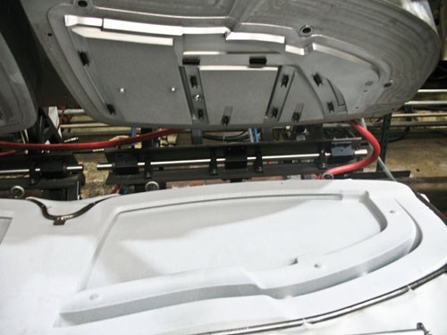
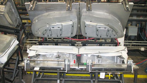
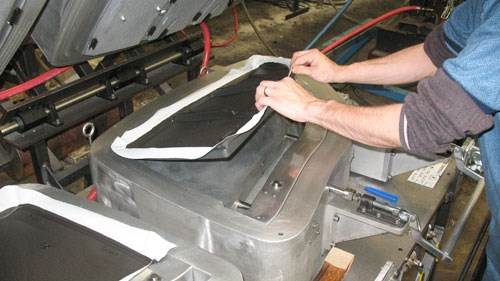
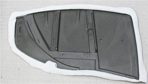
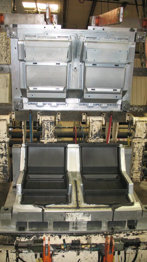
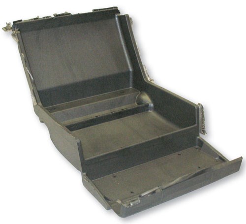
The IVCR molding process (see step photos at right) works in much the same way, with similar mold prep, vinyl layup and insert placement. Urethane resin is mixed in the same mix head and injected into the closed tools, with cure taking about the same time.
Molding of the load-bearing inner shelves is accomplished with a traditional injection molding machine equipped with a gas-assist mechanism. Gas-assist refers to the injection of nitrogen gas at low pressure into the resin melt stream immediately after the filled resin is injected into the mold. The gas moves along channels machined in the tool surface, forcing the hot resin (in this case, 20 percent chemically coupled glass-reinforced polypropylene) away from the channels. This not only helps to fill the mold, but also creates hollow cavities along the channels. Thus, less resin is used, making the process more cost-effective. Greater dimensional stability in the part also is possible because heat stresses aren’t as large a factor when the part has hollow cavities.
McAllister explains that the part was designed with grid stiffening ribs on the underside, with several of the ribs incorporating gas runners: “Thick polypropylene parts can warp during cooling, so the gas assist was selected to create a thinner shelf with reinforcing grids on the back side, some of which are hollow.” The grid design not only reduces overall part weight, but because it is thinner, the part also cools faster, with less chance for warpage. “The glass loading also helps maintain dimensional stability and reduces the part’s coefficient of thermal expansion,” he adds. Mold cooling after injection is accomplished with water channels. This “sets” the thermoplastic prior to demolding.
Over-the-road benefits
CVG is currently manufacturing the cabinets at the Concord location. Touch labor is significantly reduced because parts no longer need extensive finishing. Only trimming of excess vinyl material from the part edges and removal of flash is required. And because fasteners are received by the comolded metal inserts during assembly, drilling is not necessary, even during bin installation. McAllister explains that the bins are installed by inserting fasteners through molded-in holes in the cabinet’s one-piece back/top panel directly into the wall of the sleeper cab. (Large washers help relieve cabinet load stresses.)
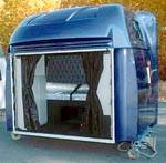
Since their unveiling at the 2010 Mid-America Trucking Show (March 2010, Louisville, Ky.) in a complete sleeper cab mockup constructed by CVG’s R&D staff, the redesigned cabinets have been well received. In addition to the overall lighter weight, McAllister points out that the cabinets provide better acoustic and thermal properties for truckers. “The new ‘no-idle’ rule in most states means that a trucker can’t sleep in the truck with the motor running,” he points out, noting that the “softer composite cabinets help muffle outside noise and provide better insulation than the previous metal and plastic design.” The cabinet represents an innovative design for manufacture that makes the most of CVG’s capabilities while providing a solution that saves both weight and cost for truckers.
Related Content
Welding is not bonding
Discussion of the issues in our understanding of thermoplastic composite welded structures and certification of the latest materials and welding technologies for future airframes.
Read MorePlant tour: Spirit AeroSystems, Belfast, Northern Ireland, U.K.
Purpose-built facility employs resin transfer infusion (RTI) and assembly technology to manufacture today’s composite A220 wings, and prepares for future new programs and production ramp-ups.
Read MorePultrusion: The basics
A primer describing what pultrusion is, its advantages and disadvantages, and typical applications.
Read MoreThe potential for thermoplastic composite nacelles
Collins Aerospace draws on global team, decades of experience to demonstrate large, curved AFP and welded structures for the next generation of aircraft.
Read MoreRead Next
Composite big-rig sleeper boxes offer comforts of home
Truckers are getting better sleep in their "homes away from home," thanks to composite sleeper boxes and cab floors manufactured by Canadian Commercial Vehicles (CCV, Kelowna, BC, Canada). Incorporated on Western Star (Willoughby, Ohio) semi-trailer trucks to decrease noise and weight and increase payload and
Read MorePlant tour: A&P, Cincinnati, OH
A&P has made a name for itself as a braider, but the depth and breadth of its technical aptitude comes into sharp focus with a peek behind usually closed doors.
Read MoreCFRP planing head: 50% less mass, 1.5 times faster rotation
Novel, modular design minimizes weight for high-precision cutting tools with faster production speeds.
Read More

