Structural work of art
Composites fabricator uses an innovative molding approach and digital techniques to actualize architect’s customized residential stairway.
The use of fiber-reinforced composites in architectural applications is on the rise, often adopted for the design flexibility they offer. This was indeed the case for a self-supporting spiral stairway for a residential project designed in 2015 by William McDonough + Partners (Charlottesville, VA, US) in partnership with stairway consultant Charlie Lovely.
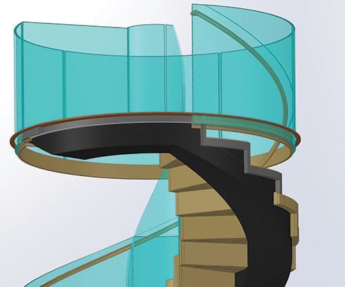
Instead of a traditional spiral staircase, where the stairs are supported from a central pole, the team conceived a stairway that would feature an outer curved spar structure from which the stairs are cantilevered with a central core that is open, termed a cascading stair. Although carbon fiber-reinforced plastic (CFRP) was a new material for the architects, it was chosen for the staircase build because the cutting, bending and final surface finishing of steel to achieve the complex design would have been prohibitively expensive. While the stairway’s outer curved spar would flaunt its carbon fiber structure visually, the CFRP stairs would be clad in white oak veneer. Glass balustrades would spiral up both sides of the stairway, supported within a groove in the CFRP structure and capped by a white oak rail.
Naval architect Eric Sponberg (Sponberg Yacht Design, St. Augustine, FL, US) was contracted as the liaison for composites structural engineering. Of the seven companies that responded to his request for proposals, and of the three short-listed for the job, selectee Clear Carbon and Components (Bristol, RI, US) was the only one with in-house 3D modeling, CNC-machining and a storyboard explaining how it would build the staircase. “The design presented a significant challenge for fabrication,” explains Clear Carbon president Matt Dunham. “No one could figure out how to make it in one piece.”
Clear Carbon and Components produces high-performance, high-quality aesthetic parts made from a wide range of composites, with special expertise in CFRP. Although a significant part of its business is high-end production parts for other companies, including musical instruments, yacht ladders and components for aerospace and naval applications, Clear Carbon has become known for developing new processes for composites projects that have hit roadblocks in manufacturing. “A lot of what we do is deciphering how to make composites production possible,” says Dunham.
With the architect’s finalized digital design files in hand, Clear Carbon began devising its plan for how to build a 4m tall, one-piece CFRP spiral spar.
Enabling a spiral tool and fixture
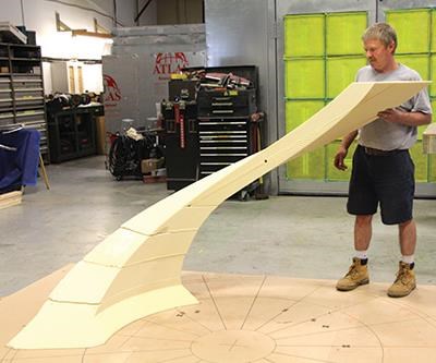
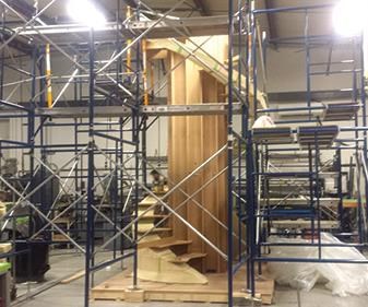
“The one-piece spar was key,” says Dunham, “not only for aesthetics, but also because it would be so structurally inefficient to break apart the unidirectional reinforcements specified in the design.” So the team focused on how to enable a one-piece layup process. Clear Carbon’s engineering manager Ben Quay invented a fixturing system that comprised a central tower to which five horizontal rods or “halos” (named after the fixture used for neurosurgery) reached out to locate and secure a spiral foam core preform (think mandrel which does not get removed). This preform would serve as the surface onto which the CFRP spar was layed up and cured (see Step 1, at left).
First, a compass rose, or reference dial, was CNC-machined into a flat, level base plate to provide a true zero from which to build the foam preform. This would enable technicians to check true position and conformance to digital design drawings throughout fabrication using a variety of tools, including a laser plumb bob. Over the compass rose, Quay built the central fixturing tower out of approximately 50 CNC-machined pieces of medium-density fiberboard (MDF) — roughly 2.4m long by 0.4m wide and 15.2 cm thick — which fit together like a puzzle. Next, five “halo” bars were attached, recalls Dunham. “These projected out like arms to position the foam preform in mid-air,” he explains, “and also to position the stairs at the various heights and angles that they needed to be.” (See Step 2).
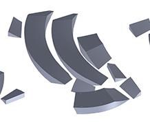
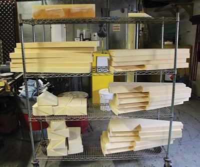
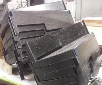
Because the layup preform would not have to carry structural load, it was made from 13 pieces of easy-to-machine rigid urethane foam sourced from Poly Cel (Stow, MA, US) and cut using Clear Carbon’s 3-axis CNC mill (see Fig. 1, at left). Dunham says the 3D modeling and CNC machining for the fixturing tower and preform was the part of the project that went the fastest, completed in less than two days. Holes were machined into each foam preform component, enabling them to be assembled vertically, glued and then held together with dowels until the adhesive set. The foam preform was then “rigidized” using three layers of Sigmatex (Benicia, CA and Cameron, SC, US) 400-g/m2 double-bias carbon fiber fabric, supplied by Core Composites (Bristol, RI, US), which was wet laminated with room-temperature cure PRO-SET epoxy resin (Gougeon Brothers, Bay City, MI, US).
Clean lines, multi-step process
Although the cured preform could now support layup, it first had to be sanded to achieve the clean, sharp lines essential to the stair design. Next, a prepreg resin film was applied to provide a chemical bonding layer for the spar’s structural layup: 10 plies of 600-g/m2
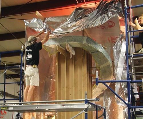
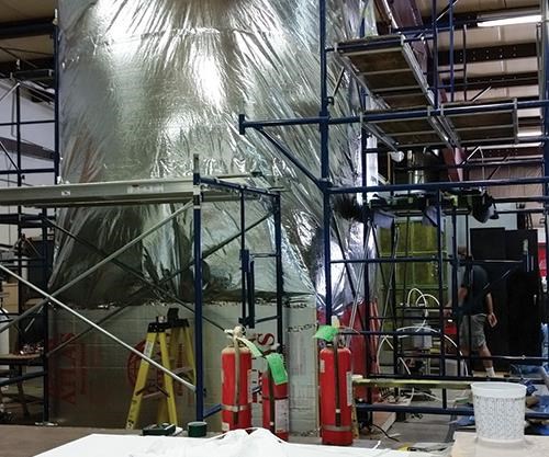
Gurit (Bristol, RI, US) carbon fiber/epoxy unidirectional prepreg. Because there was no tool surface to which technicians could tacky-tape the vacuum bag, the entire vertical layup was enveloped in vacuum bag film (a technique known as “envelope bagging”) for intermediate debulks and final cure. The spar layup was debulked every few plies and, for cure, it was enclosed in a temporary oven made using a 3M (Minneapolis, MN, US) metallized Mylar film, which had a much higher temperature rating than typically used visqueen polyethylene sheeting (Step 3a & b). This was key, because the spar’s 91°C cure temperature exceeded visqueen’s 82°C maximum service temperature. Digital controllers used temperature data from thermocouples applied prior to vacuum bagging to cycle propane heaters on and off as needed without overheating during the 6-hour cure.
After cure, the spar was debagged and sanded before application of two layers of double-bias carbon fabric, prepregged with the same Gurit low-temperature-cure epoxy resin. Then the spar layup was re-bagged and put through another 6-hour cure.
The wedges were positioned on the spar using the central MDF fixture and bonded in place with PRO-SET 176/276 structural epoxy adhesive (Step 5a & b). Each marked where a stair would be located. Its position was checked, using lasers, against the compass rose and plumb baseplate.
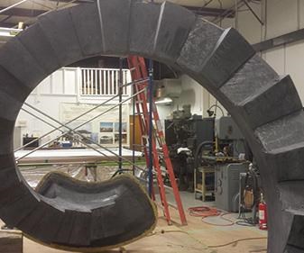
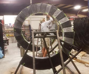
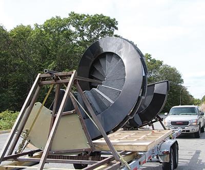
At this point, the staircase resembled a tall corkscrew with sawteeth. The center scaffold and halo fixturing were disassembled and the stairway was mounted into a rotisserie fixture made from steel boxstock (Step 6), which enabled easy rotation of the structure as the spar surface was faired (made smooth) with epoxy filler and then received two final plies of 200-g/m2 2x2 twill CF prepreg to provide the visual carbon surface.
“We actually turned the whole stairs upside down to make it easy to apply the cosmetic layer and get the fiber orientation right for the aesthetic appearance,” says Dunham.
Envelope bagging and cure in the temporary oven were repeated, followed by a final 6-hour post-cure at 90°C. After demolding, multiple layers of high-gloss clearcoat were applied.
Finishing steps
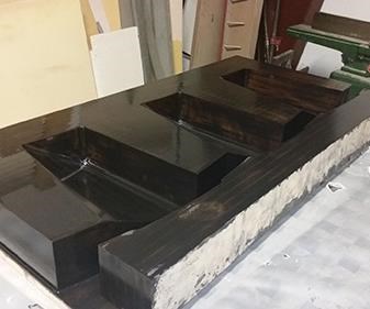
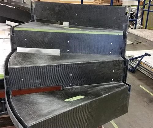
The spar with wedges was again repositioned, vertically (right side up), and fitted with another central MDF fixture, but this one was narrower to accommodate location and placement of the 91-cm-wide stairs. Each stair unit had been molded with a groove at both inner and outer edges to eventually receive the glass balustrades (see top image at left) upon installation in the residence (Step 7a & b). Finally, 19 stair units and one landing were bonded to the wedges, again using the PRO-SET 176 adhesive.
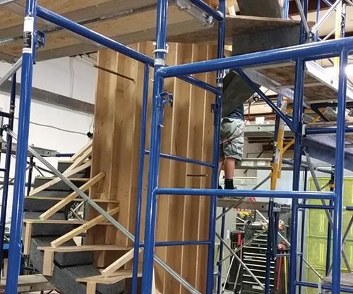
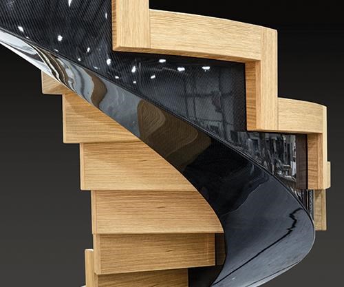
The narrower fixturing tower was removed and the staircase was reinserted into the rotisserie fixture, which now served as a shipping fixture to transport the finished structure by road to East Coast Interiors (North Dartmouth, MA, US), a producer of high-quality yacht and jet aircraft interiors, where white oak veneers were applied to the stair treads and risers (see the result in Fig. 2, last image on left). The stairway was scheduled to receive its glass sides and white oak rails during installation at the customer’s residence in January.
Why use CFRP stairs if they were going to be covered with wood? “We knew early on in the engineering process that the design was stiffness-critical,” says naval architect and composites structure liaison Sponberg. “We imagined the worst-case scenario of a person (≈84 kg) on every stair during a party and wanted less than 3.2 mm of deflection in each stair. Even with the staircase simply bolted to the shop floor and to the steel pipe scaffolding at Clear Carbon, we could tell there was tremendous rigidity in the freestanding structure.”
Sponberg is very pleased with the final outcome, noting “the whole project went so smoothly and according to plan, and the shiny carbon surfaces you see as you walk up and down the stairs are exactly what the customer wanted and what we knew Clear Carbon could produce.” In fact, the surfaces are so pristine, they create the illusion of a secondary piece made and applied to the stairs. In the image of the stairs fitted with step veneers (Fig. 2), the visible carbon fiber exemplifies the flawless mirror finish achieved over the entire expanse of the spar’s visible surface.
“This was a very complicated but successful project for us,” says Dunham. “It stretched us technically, but in the end we achieved our goal: a structural work of art.”
Related Content
XlynX’s PlastiLynx PXN crosslinking primer enhances polymer adhesion
PFAS-free diazirine primer makes surfaces receptive to all manner of adhesives, including epoxies and polyurethanes, outperforming alternative options by 150-350%.
Read MoreFilm adhesive enables high-temperature bonding
CAMX 2024: Aeroadhere FAE-350-1, Park Aerospace’s curing modified epoxy, offers high toughness with elevated temperature performance when used in primary and secondary aerospace structures.
Read MorePittsburgh engineers receive $259K DARPA award for mussel-inspired underwater adhesion
The proposed META GLUE takes inspiration from hydrogels, liquid crystal elastomers and mussels’ natural bioadhesives to develop highly architected synthetic systems.
Read MoreHenkel releases digital tool for end-to-end product transparency
Quick and comprehensive carbon footprint reporting for about 58,000 of Henkel’s adhesives, sealants and functional coatings has been certified by TÜV Rheinland.
Read MoreRead Next
“Structured air” TPS safeguards composite structures
Powered by an 85% air/15% pure polyimide aerogel, Blueshift’s novel material system protects structures during transient thermal events from -200°C to beyond 2400°C for rockets, battery boxes and more.
Read MoreModeling and characterization of crushable composite structures
How the predictive tool “CZone” is applied to simulate the axial crushing response of composites, providing valuable insights into their use for motorsport applications.
Read MoreVIDEO: High-rate composites production for aerospace
Westlake Epoxy’s process on display at CAMX 2024 reduces cycle time from hours to just 15 minutes.
Read More



.jpg;maxWidth=300;quality=90)
