
MTI Valve unveiled as innovative solution in resin infusion
New resin inlet valve touted as easy, low-cost way to ensure laminate compaction and “optimal” fiber volume fraction.


The vacuum infusion/resin infusion process is a leading technology for the production of a large variety of composite structures. However, users can find it difficult to achieve consistent results and avoid failures without proper process control. DD-Compound (Ibbenbüren, Germany), with distribution and technical support in the U.S. via German Advanced Composites (Miami, Fla.), first developed Membrane Tube Infusion (MTI) Hose to help ensure sufficient process control and high-quality results with vacuum infusion. (See Feb 2014 CT article, “Semipermeables: Next trend in infusion?”) Now the company has introduced MTI Valve which targets control of the preform compaction and pressure gradient during infusion, reportedly resulting in a higher fiber volume fraction, reduced thickness gradient and improved overall quality in the part.
Resin infusion requires a pressure differential across the part layup to drive resin flow. The traditional approach is to place the layup under a vacuum bag, apply vacuum, and then open the inlet for the resin from the reservoir, which is at ambient pressure (open to atmospheric pressure). German Advanced Composites shows the following diagrams to explain the pressure state through this process.


Physics behind vacuum infusion. SOURCE: DD-Compound.
Prior to evacuation the mold, dry preform, flow media and vacuum bag are all in a relaxed state. At this point, the pressure within the bagged system is the same as that outside of the bagged system, namely atmospheric pressure. Thus, the net pressure compacting the dry preform is zero.
After evacuation and prior to resin flow, vacuum has been applied so that absolute pressure is uniformly low (vacuum is uniformly high) and the mold, preform, flow media and vacuum bag are in a compacted state. German Advanced Composites asserts that, for a high quality infusion, the goal is to achieve an absolute pressure in the range of 10 mbar inside the bagged system, while 1000 mbar remains outside the bagged system. Thus, the pressure differential is 990 mbar, which is the net compaction pressure upon the dry preform.
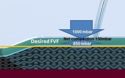
Once the resin inlet is opened, the resin begins to flow and the pressure of the filled volume approaches atmospheric pressure, which is the pressure at the reservoir. The rise in pressure inside the bagged system acts against the atmospheric pressure outside the bagged system. The pressure differential is the remaining net compaction upon the preform in the mold, as shown in the diagram below.

Net pressure upon the preform after resin flow begins.
SOURCE: DD-Compound.
This pressure differential will vary depending on a number of factors including the permeability of the dry preform and flow media and the timing sequence of clamping the resin inlet(s) and vacuum lines. With less compaction, more resin can flood the preform. In traditional resin infusion, this net compaction can approach zero, resulting in laminate relaxation which leads to increased thickness and reduced fiber volume fraction.
This is precisely what the Boeing patented Controlled Atmospheric Pressure Resin Infusion (CAPRI) method was developed to remediate. CAPRI places the resin reservoir under a partial vacuum to reduce the pressure differential between the resin inlet and the vacuum lines. As stated in the patent, the goal of CAPRI is to ensure “that the fiber plies in the preform will remain compacted, that the preform is completely filled when the infusion is halted, and that optimum fiber volume fractions are achieved. . . .”
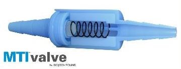
Though the industry has developed a variety of other methods to address this compaction and laminate relaxation issue, the MTI Valve is touted as perhaps the most simple and cost-effective solution, without dependence upon lengthy training. According to German Advanced Composites CEO, Juergen Schildgen, “Simply plug the MTI Valve into the resin feed line and it will control the pressure in the bagged system by reducing the pressure within the resin inlet tube, and thus maintaining a net compaction pressure to achieve optimal fiber volume fraction.” He adds that MTI Valve works by integrating a defined resistance into the resin inlet line. This defined counterpressure can be adjusted through use of different springs inside the valve, depending upon the desired fiber volume fraction. For now, the MTI Valve is designed to produce a laminate with roughly 55 percent fiber volume fraction using non crimp fabrics. DD-Compound is evaluating offering different valve designs in the future.
Schildgen says that using the MTI Valve in conjunction with the MTI Hose creates a closed hydraulic system that is designed to be self-regulating in terms of resin flow management, leaving less room for failure and increasing the ability to repeatedly achieve void-free laminates. He also claims that the MTI valve eliminates the need to clamp the resin inlet line. Schildgen explains, “As soon as the pressure in the bagged system reaches the designed limit of the MTI Valve — 850 mbar in the example below — the valve shuts off the resin flow and a further rise of pressure within the bagged system is not possible.”
Resin infusion using MTI Valve. SOURCE: DD-Compound.
The video below gives a demonstration of how the MTI Valve works.


.jpg;maxWidth=300;quality=90;format=webp)


Related Content

TPRC training courses target thermoplastic composites
Three upcoming in-person thermoplastic composites courses, ranging from entry-level to advanced, are organized to enhance composites professionals’ knowledge in this burgeoning field.
Read More
Automated filament winding system increases throughput, reduces manual labor for pressurized well tank production
For its new line of composite well water tanks, Amtrol worked with Roth Composite Machinery on an automated process for faster, more easily tracked production.
Read More
ASCEND program update: Designing next-gen, high-rate auto and aerospace composites
GKN Aerospace, McLaren Automotive and U.K.-based partners share goals and progress aiming at high-rate, Industry 4.0-enabled, sustainable materials and processes.
Read More
9T Labs, Purdue University to advance composites use in structural aerospace applications
Partnership defines new standard of accessibility to produce 3D-printed structural composite parts as easily as metal alternatives via Additive Fusion Technology, workflow tools.
Read MoreRead Next

“Structured air” TPS safeguards composite structures
Powered by an 85% air/15% pure polyimide aerogel, Blueshift’s novel material system protects structures during transient thermal events from -200°C to beyond 2400°C for rockets, battery boxes and more.
Read More
Plant tour: Teijin Carbon America Inc., Greenwood, S.C., U.S.
In 2018, Teijin broke ground on a facility that is reportedly the largest capacity carbon fiber line currently in existence. The line has been fully functional for nearly two years and has plenty of room for expansion.
Read More
The next-generation single-aisle: Implications for the composites industry
While the world continues to wait for new single-aisle program announcements from Airbus and Boeing, it’s clear composites will play a role in their fabrication. But in what ways, and what capacity?
Read More