
Superbeam: Steel and carbon fiber work together to revolutionize structural elements
New approach to CFRP-strengthened steel beams increases load capacity by >75%, enabling dramatic downsizing while maintaining traditional bolted and welded attachments.


The idea of strengthening a steel beam with carbon fiber is not new. Approaches have ranged from coating corroded steel i-beams with carbon fiber and epoxy to a patent by Boeing where carbon fiber reinforced plastic (CFRP) plates are used to strengthen i-beam flanges.
The patent awarded to AJ Cesternino, founder of Wingman Industries (Callaway, VA, US), takes a different approach. Using CFRP in the flanges does indeed place the material in the highest-stress regions of the beam, and thus, uses it to the greatest advantage strength-wise. However, it does not solve the problem of how to attach this beam without drilling through the fibers, nor potential issues with delamination. However, by embedding the CFRP within the web of the i-beam, the new Superbeam not only enables standard bolting to flanges but also increases the ultimate load by more than 75% vs. an unreinforced steel i-beam.


Test results of CFRP-strengthened steel Superbeam vs. unreinforced steel i-beam.
Developing the Superbeam Concept
Superbeam’s inventor, AJ Cesternino, has spent more than 40 years in the trucking industry. “Like many, I’ve been waiting for the benefits of carbon fiber to reach my industry,” he says. Although there have been development projects, like the Walmart Advanced Vehicle Experience and the US Dept. of Energy’s SuperTruck program, there haven’t been any significant applications of carbon fiber reinforced plastic (CFRP) in trailer chassis.
Tired of waiting, Cesternino set out to improve steel beams used in truck trailer chassis, but quickly saw the issues introduced above: how to strengthen the beams in a way that avoids drilling through fibers when creating bolt holes and how to attach the CFRP to the steel without the risk of delamination?
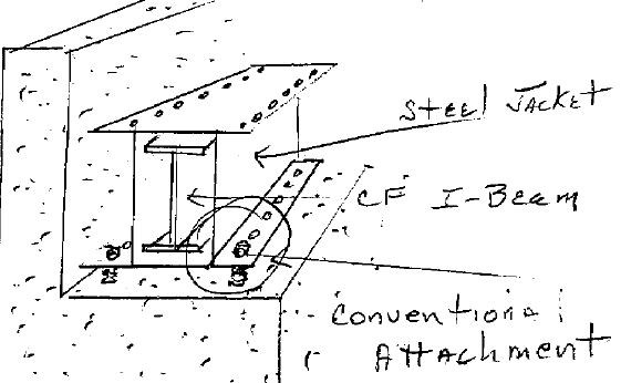
Cesternino’s concept was to use a steel i-beam with two webs. The CFRP strengthening element could then be inserted between the two webs, keeping the flanges free for standard bolted attachments. To create the double-web beam in-house, Cesternino simply welded two i-beams together.
The next step was developing the CFRP reinforcing member. Pultruded CFRP i-beams are readily available from multiple suppliers in a range of widths and depths, and at lengths feasible for use in trailer chassis. Though Cesternino’s later efforts did use these, his initial development started from scratch, manufacturing a rectangular beam from 220 layers of carbon fiber/epoxy prepreg supplied by Hexcel (Stamford, CT, US) and a home-built autoclave.
Cesternino then devised a solution for attaching the CFRP beam within the double webs of the steel beam. By injecting an epoxy compound — between 0.125 and 0.25 inch (3.2-6.4 mm) thick — into that space, he could bond the CFRP to the steel i-beam, surround and protect the CFRP from damage and absorb any differences in expansion/deformation between the CFRP and steel due to temperature and load.
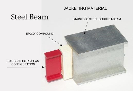
Wingman Industries’ Superbeam bonds a carbon fiber composite strengthening beam between the webs of a double web steel i-beam using an epoxy compound. SOURCE: Wingman Industries.
“Protecting the CFRP strengthening element is important,” Cesternino notes, “because significant hits during installation and service can cause microcracks, which can then grow to weaken the structure.” He adds that the two-part epoxy elastomer develops a shore hardness of 95 and is “as durable as truck tire rubber. It also acts as a vibration damper in the CFRP-strengthened Superbeam.”
Testing the Superbeam Concept
In 2009, Cesternino sent his original demonstration Superbeam to the Composite Materials and Engineering Center (CMEC) at Washington State University (WSU, Pullman, WA, US) for testing and evaluation. The test beam was roughly 9 ft (2.7m) long, 5.375 in (137mm) wide and 4 inches (102mm) in depth, made from welding two S4x7.7 stainless steel i-beams together, with the prepreg CFRP beam — measuring roughly 2 inches by 3-inches (51 mm by 76 mm) — located between and bonded to the steel webs using an epoxy elastomer compound. This CFRP-steel Superbeam was tested using three-point loading and a simple beam bending setup with supports set 100.8125 inches (2.56 m) apart. Single-point loading was applied mid-span at a speed of 0.5 inch (12.7 mm) per minute to a maximum load of 43,909 lbs with a centerline deflection of 4.17 in (106 mm) and shear failure in the CFRP beam.
Though a double-web stainless steel i-beam without CFRP was not tested, its failure load was calculated to be 10,094 lb using standard engineering mechanics and an assumed yield stress of 42,050 psi. A CFRP i-beam was tested by itself, achieving a final load of 10,462 lb with a 3.59-inch (91-mm) deflection.
CMEC reported that the CFRP-strengthened steel Superbeam showed a 92% higher yield strength than the stainless steel beam by itself, while its loading capacity was 103% higher vs. the stainless steel beam.
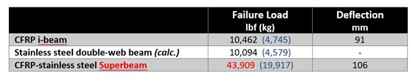
2009 Superbeam test results from CMEC at WSU.
SOURCE: Wingman Industries and CMEC, Washington State University.
Encouraged by these initial test results, Cesternino continued developing the Superbeam concept and performed a second round of testing in 2016, using an independent testing company, Applied Technical Services, Inc. (Chesapeake, VA, US). Three-point bending was again applied to a double-web steel i-beam, a pultruded CFRP i-beam from Strongwell (Bristol, VA, US) and a Superbeam where the pultruded CFRP was bonded to the steel using an epoxy compound. Supports were 9 ft (2.7m) apart and beams were loaded mid-span using a 2.5-inch (63.5-mm) aluminum roller at a rate of 0.125 inch (3.2mm) per minute.
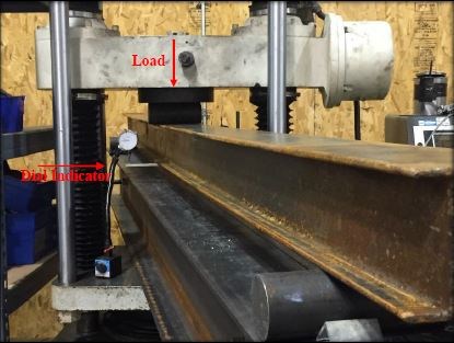
Steel i-beam in 3-point bending test setup at Applied Technical Services.
SOURCE: Wingman Industries and Applied Technical Services.
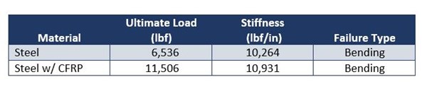
In this second round of testing, the CFRP-strengthened steel Superbeam showed a 76% increase in load capacity over the unreinforced steel i-beam. Though the CFRP rectangular beam made from prepreg in the initial testing at WSU was much higher performing than the pultruded CFRP i-beam tested at ATS, the former was prohibitively expensive.
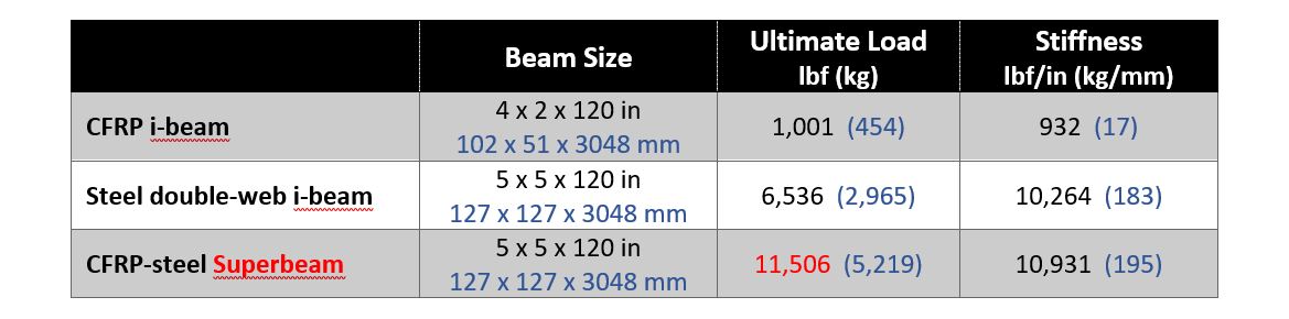
Superbeam test results from 2016 testing at Applied Technical Services, Inc. SOURCE: Wingman Industries and ATS.
Proceeding toward commercialization
Cesternino explains the possible benefits of using Superbeam, “Instead of a standard 36-inch beam, you could use a 16- or 18-inch beam to handle the same loads. That smaller beam requires less steel, is lighter weight, easier to transport and easier to install.” Alternatively, it is possible to stay with a currently specified beam size, but use Superbeam to dramatically increase its load capacity.
Because Superbeam flanges are easily bolted to existing structure, it can be used to retrofit bridges and other infrastructure, extending service without interrupting traffic during installation. SOURCE: Wingman Industries.
“We’ve developed a bridge retrofit system, where we can weld or bolt the Superbeam onto current girders without stopping traffic and extend the service life of the bridge by at least 50-60 years,” says Cesternino. Other applications being pursued include high-load/reduced weight truck trailers and multi-level trailers, RV and camper chassis, etc. The basic concept has also been extended to rods, truss structures and railroad ties.
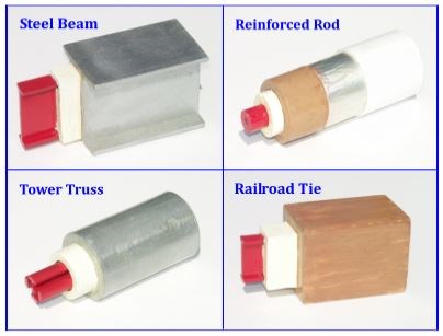
The Superbeam concept has been extended to provide reduced weight and improved load capacity for rods, truss structures and railroad ties.
SOURCE: Wingman Industries.
“I believe this could transform not only our current crisis in corroded infrastructure, but also provide revolutionary improvements in transportation and a wide variety of construction projects,” says Cesternino. He notes that previous all-composite beams have been rejected by state Dept. of Transportation (DOT) engineers because of the issues with fastening, microcracks and delamination. Superbeam, however, has been well received by the Virginia state DOT, with discussions in progress on possible demonstration projects.
Further validation of Superbeam has come from Cesternino’s steel beam manufacturing partner throughout this development, Valta Crane Systems (Brantford, ON, Canada). This manufacturer of overhead cranes would also like to see Superbeam commercialized, because it offers crane beams that require less steel, are lighter, and thus require less supports, but most importantly beam height could be reduced by 50%. This provides an additional 1-2 ft (0.3-0.6 m) of vertical clearance, especially attractive for buildings where the only solution currently is to raise the ceiling/roof.
Cesternino is now focused on working with industry partners to industrialize Superbeam production and achieve cost parity with traditional steel beams based on improved weight, load-capacity and installation. He is also exploring simplifying the CFRP i-beam back to a simple rectangular beam/plate. Cesternino notes that any lateral loads can be sufficiently handled by the steel i-beam flanges. He looks forward to ideas from composite materials suppliers and fabricators about how to produce these CFRP beams most cost-effectively. Contact ajwingman@gmail.com.


Related Content

Cryo-compressed hydrogen, the best solution for storage and refueling stations?
Cryomotive’s CRYOGAS solution claims the highest storage density, lowest refueling cost and widest operating range without H2 losses while using one-fifth the carbon fiber required in compressed gas tanks.
Read More
Thermoplastic composites: Cracking the horizontal body panel nut
Versatile sandwich panel technology solves decades-long exterior automotive challenge.
Read More
TPI manufactures all-composite Kenworth SuperTruck 2 cab
Class 8 diesel truck, now with a 20% lighter cab, achieves 136% freight efficiency improvement.
Read More
Plant tour: Joby Aviation, Marina, Calif., U.S.
As the advanced air mobility market begins to take shape, market leader Joby Aviation works to industrialize composites manufacturing for its first-generation, composites-intensive, all-electric air taxi.
Read MoreRead Next

All-recycled, needle-punched nonwoven CFRP slashes carbon footprint of Formula 2 seat
Dallara and Tenowo collaborate to produce a race-ready Formula 2 seat using recycled carbon fiber, reducing CO2 emissions by 97.5% compared to virgin materials.
Read More
“Structured air” TPS safeguards composite structures
Powered by an 85% air/15% pure polyimide aerogel, Blueshift’s novel material system protects structures during transient thermal events from -200°C to beyond 2400°C for rockets, battery boxes and more.
Read More
Plant tour: Daher Shap’in TechCenter and composites production plant, Saint-Aignan-de-Grandlieu, France
Co-located R&D and production advance OOA thermosets, thermoplastics, welding, recycling and digital technologies for faster processing and certification of lighter, more sustainable composites.
Read More