Aeroengine Composites, Part 1: The CMC invasion
As pressure for commercial aircraft fuel efficiency continues to mount, ceramic matrix composites evolve as they battle metals for application in the engine hot-zone and elsewhere.
The airlines’ push for jet engine fuel efficiency shows no signs of abating. CW reported earlier this year that the average fuel burn per aircraft seat-km today compared to 1980 has been reduced by 27% for widebody aircraft and 35% for narrowbody models (see “Composites in commercial aircraft engines: 2014-2023,” under "Editor's Picks," at top right). But more ambitious reductions have been called for by the Advisory Council for Aviation Research in Europe (ACARE) in Flightpath 2050 — a 75% reduction in CO2 per passenger-km, a 90% reduction in nitrous oxide (NOx) emissions and a 65% reduction in noise by the year 2050 vs. performance levels recorded in 2000. The dire need for, and rather drastic depth of, such reductions are precisely the sort of situation where the subject of this report, composite matrix composites (CMCs), promise a solution.
Although they’re considerably more expensive — reportedly hundreds to thousands of dollars per kilogram — they are roughly one-third the weight and twice the strength of the nickel alloys currently used in jet engines, and they offer a 100-200°C improvement in high-temperature capability. No surprise, then … they’re now in demand.
Engine application landscape
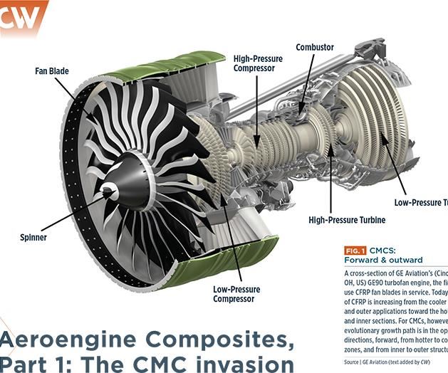
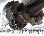
Notably, carbon fiber reinforced polymer (CFRP) composites (the subject of Part 2, which will appear in CW September) continue on an upward growth curve, but CFRP and CMC growth trajectories are on something of a collision course. According to Henrik Runnemalm, director of advanced engineering for Tier 1 supplier GKN Aerospace (Redditch, UK), “CFRP products are moving mainly from the front of the engine towards the back and also from the outside, moving inward.” With much higher temperature resistance, CMCs are moving in the opposite direction, i.e., from the rear — the engine “hot zone” — towards the front and from the inside towards the outside (see Fig. 1, at left). “There will always be a mix of materials,” says Runnemalm, observing that integration of CFRP, CMCs and metals will be a challenge, including joining techniques, how to deal with the stress distribution, assembly and disassembly requirements and managing the transition between heat zones in the engine.
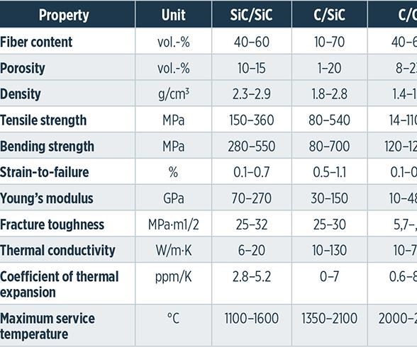
The main types of CMCs include silicon carbide (SiC) fibers reinforcing a SiC matrix (SiC/SiC), carbon/carbon (C/C), C/SiC and Ox/Ox where the oxide is typically alumina (see Table 1, at left). SiC/SiC components used in oxidation-causing environments must be protected, using environmental barrier coatings (EBCs), and even the SiC fibers must be coated to prevent attack from oxygen molecules diffusing through the porous matrix. Because they do not require a carbon coating on the fibers or EBCs, Ox/Ox composites offer lower cost. However, they lag in thermomechanical properties vs. SiC/SiC.
CMCs take flight
GE Aviation (Cincinnati, OH, US) expects a tenfold increase in the use of CMCs in its engines over the next decade (readm ore in “Ceramic-matrix composites heat up” under "Editor's Picks"). One reason is that, unlike metals in the hot zone, CMCs don’t need to be air-cooled, freeing up flow to boost the engine’s propulsion and efficiency.
GE’s first CMC parts to enter service will be the static first stage HP compressor shroud in the LEAP engine. Also called HP turbine shrouds, and reportedly some of the hottest parts in a turbofan, 18 of these direct airflow to ensure turbine blade efficiency. They are manufactured using SiC/SiC at GE’s CMC-dedicated Asheville, NC, US, factory, which also will make the inner and outer combustion liners and stage 1 and 2 nozzles for the GE9X engine.
These parts not only reduce cooling air requirements but also improve durability. Finished parts from Asheville will proceed to Advanced Ceramic Coatings (ACC, Hickory, NC), which operates from the US facility of surface treatment specialist Turbocoating (Rubbiano di Solignano, Italy). ACC will apply GE’s proprietary EBCs to protect SiC/SiC components from surface recession (erosion) and expects to deliver its first coated parts later this year.
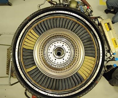
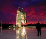
Although CMCs were first targeted to static applications, the real revolution, say proponents, will come with dropping weight and cooling in rotating parts. In February 2015, GE successfully tested CMC rotating parts in an F-14 military jet engine. Similar to the fan disk reduction enabled by CFRP fan blades, these CMC LP turbine blades allow smaller, lighter metal turbine disks (see Fig. 2) and bearings and other parts can be downsized, multiplying weight savings by as much as a factor of three.
According to GE Aviation’s CMC design section leader Jonathan Blank, replacing nickel alloys with CMCs inside the engine is a huge step and sets the stage for revolutionary jet engine design changes. GE is also exploring use of CMCs in helicopter engines and in gas turbines and compressors for electrical power plants.
At Rolls-Royce (Manchester, UK), researchers tested SiC-SiC HP turbine blade tracks in 2013 and then SiC-SiC shroud segments, using a Trent 1000 test engine via the Environmentally Friendly Engine (EFE) program. The blade tracks — which could reduce component weight and engine cooling by 50% — also were key demonstrators in the US Federal Aviation Admin.’s (FAA, Washington, DC, US) Continuous Lower Energy, Emissions, and Noise (CLEEN) program. Testing is scheduled to run through 2015.
The higher pressure ratios planned in Rolls-Royce’s Advance and UltraFan engines mean higher operating temperatures and increased NOx emissions — increases that could be mitigated through the use of CMCs. The company says it will definitely use CMCs in static parts, such as nozzles, and in its Vision10 (technology-ready in 10 years) strategy outline, its HP turbine goes shroudless, using, instead, a CMC liner.
Pratt & Whitney (Hartford, CT, US) has said it sees low value for CMCs in static applications and, therefore, will focus CMC application efforts on rotating turbine blades and the combustor. In 2010, Pratt & Whitney Canada (P&WC, Longueuil, QC, Canada) tested a CMC reverse-flow combustor in a PW200-series rotorcraft engine, achieving a 30% NOx reduction at high power and a 20% cut in CO at low power vs. the standard metal unit. Patent application US 2014/0311152 A1 describes the annular combustor as having an inner liner comprising a dome portion, a small exit duct portion and a large exit duct portion, each an independently formed hemi-toroidal CMC shell. Although the combustor sees the highest temperatures in this engine, holes for cooling air delivery are not necessary, so no machining is required after liner sections are formed.
In 2015, P&WC presented results from computer analysis of thermal stresses on a combustor molded with Ox/Ox materials from COI Ceramics (San Diego, CA, US). It analyzed flat and curved segmented panels as well as 360° annular parts and identified potential for delamination at temperature transitions and panel edges, tensile rupture on the cool side, and compressive damage accompanied with fiber buckling on the hot side and panel edges. However, adding an insulation layer reduced stresses by a factor of three.
Upping performance at the exit
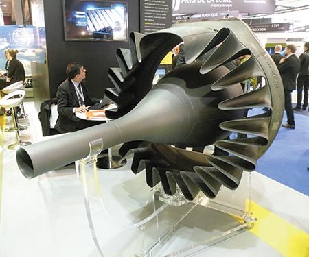
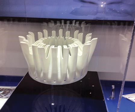
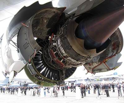
Herakles (Le Haillan, France), a subsidiary of Paris, France-based Safran, has been working on a series of CMC parts for the next generation of LEAP engines as well as new Safran-designed engines targeting the 2020-2030 timeframe. On June 16, it announced that its SiC-based exhaust cone is the first CMC part to fly on a jetliner in commercial service (Read more online about Herakles’ CMC exhaust cone in the CW Blog titled “Highlights: JEC Europe 2014” under the heading “CMC exhaust cone for LEAPX engines” by clicking here. Fastened directly to the aft flange of the CFM56 test engine’s turbine frame, and interfaced with the nacelle, the exhaust cone comprises a centerbody and a complex “lobed” shape mixer. The latter achieves optimal mixing of the hot engine gases with the cold bypass air, improving the engine exhaust system’s output and efficiency (see Fig. 3). Measuring 1,625 mm in length and 655 mm in diameter, the exit cone weighs a mere 24.5 kg. European Aviation Safety Agency (EASA, Cologne, Germany) certification for use on commercial flights slated for 2013 was finally received April 22, 2015. The company has completed demonstrations of other new commercial aeroengine applications:
- Prototype CMC mixers ground-tested on a CFM56-5C engine and flight-tested on an Airbus Helicopter (Marignane, France) Tiger rotorcraft.
- In-flight test of a CMC trailing-edge fairing on an A380 engine pylon.
- CFM56 engine ground-test of CMC LP turbine blades.
NASA’s (Washington, DC, US) efforts to mature CMC applications include a SiC/SiC combustor liner, SiC/SiC HP turbine vane, and an Ox/Ox exhaust nozzle through its Environmentally Responsible Aviation (ERA) project. This six-year project’s Phase II culminates in 2015 with Integrated Technology Demonstrations (ITD) of downselected technologies to reach technology readiness level (TRL) 6. Advanced EBCs tailored for the combustor and vane are in development for surface temperatures to 1482°C, while the exhaust nozzle is targeted for service at 816°C.
In summer 2014, Boeing successfully ground- and flight-tested its Ox/Ox exhaust nozzle, developed through the CLEEN program. Results showed better thermal performance than Inconel at a weight 20% less than titanium, noise performance the same or better than metal and continuous operation at 816°C. Rated at TRL 7, a second design cycle is reportedly slated for 2015 with partners Rolls-Royce, Orbital ATK (Dulles, VA, US), American Airlines (Fort Worth, TX, US) and Albany Engineered Composites (AEC, Rochester, NH, US).
AEC, which worked with Boeing to develop the CLEEN nozzle’s CMC substrate, is additionally exploring the ability to combine CMC and 3D woven composite technology. AEC’s VP of research and technology Brian Coffenberry sees the potential for these combined technologies to improve toughness. Also, because of the automation already associated with 3D composites, the fabrication processes might also become highly scalable.
In 2014, Composites Horizons (Covina, CA, US) added a 3,252m2 CMC-dedicated facility as well as a new autoclave, sintering ovens and CNC equipment after receiving the production contract for nozzle components in GE’s Passport 20 engine, which will power Bombardier 7000 and 8000 ultra-long range business jets. According to GE director of Bombardier programs Judd Tressler, Ox/Ox CMC replaces what would have been graphite/epoxy in the four-piece panel that encloses the engine core and the nine-piece mixer (see Fig. 4). Saving roughly 20 kg in the mixer alone, GE selected Ox/Ox for the Passport 20 in 2010 to help reduce engine weight.
As CMCs move outward and forward, they’ll continue to be pushed toward higher operating pressure ratios in the hot zone. Slated objectives include next-generation turbine disk materials, an 820°C-capable compressor and 1,650°C turbine blades/vanes. But having pierced the veil, CMCs are already closing in on these targets. The challenge now will be to extend thermomechanical performance while at the same time enhancing manufacturing robustness and reducing per-unit cost.
Read Part 2 of the series: “Aeroengine Composites, Part 2: CFRPs expand”
Related Content
New CMC turbine vanes successfully tested in wind tunnel
SiC/SiC ceramic matrix composite (CMC) inlet guide vanes for a high-pressure turbine are aimed for a geared turbofan and show promise for more efficient aeroengines with less weight and need for cooling.
Read MoreDITF Denkendorf advances sustainable carbon fibers, oxide fibers for CMC and more
The German Institutes of Textile and Fiber Research are targeting more sustainable carbon fiber via low-pressure stabilization and bio-based precursors, and working with Saint-Gobain to commercialize oxide ceramic fibers for CMC.
Read MoreBombardier begins manufacture of Global 8000 business jet
Ultra-long range business jet featuring CMC-intensive engine and a range of 8,000 nautical miles is set to enter service in second half of 2025 as it remains on track for flight testing.
Read MoreSRI advances CMC for solar, renewable energy and industry
U.S. research institute advances “infiltration-free” process for improved performance, durability and affordability of materials able to withstand highly corrosive environments at temperatures beyond 700°C.
Read MoreRead Next
Composites in commercial aircraft engines, 2014-2023
The drive to boost aircraft operating efficiency continues to fuel adoption of polymer matrix composites in jet engines.
Read MoreCeramic-matrix composites heat up
Lightweight, hard and stable at high temperatures, CMCs are emerging from two decades of study and development into commercial applications.
Read More“Structured air” TPS safeguards composite structures
Powered by an 85% air/15% pure polyimide aerogel, Blueshift’s novel material system protects structures during transient thermal events from -200°C to beyond 2400°C for rockets, battery boxes and more.
Read More

