Plant Tour: GE Aviation, Asheville, NC, US
An avant-garde approach to unprecedented CMC parts production.
GE Aviation (Evendale, OH, US) has spent more than US$1.5 billion to bring to market ceramic matrix composites (CMCs) that can be mass produced. The quantity of CMC raw material GE uses has increased twenty-fold in the past decade alone. By 2020, GE Aviation expects to have established the first vertically integrated CMC supply chain in the US, with roughly 750 employees producing up to 20,000 kg/yr of CMC prepreg and 10,000 kg/yr of SiC fiber.
More than 20 years in the making, this CMC technology originated at GE’s Global Research Center (GRC, Niskayuna, NY, US), was incubated at its CMC Lean Lab and FastWorks Lab (Evendale, OH, US), and was scaled up at the GE CMC low-rate initial production (LRIP) center (Newark, DE, US). As the company has foreseen the future of advanced manufacturing and invested heavily in 3D printing and digital thread/digital twin/Big Data technology, it has also laid a robust foundation for exploiting advanced CMCs’ potential to deliver the increased performance, reduced weight and emissions and lower operating cost being demanded for the jet engines that will power tomorrow’s aircraft.
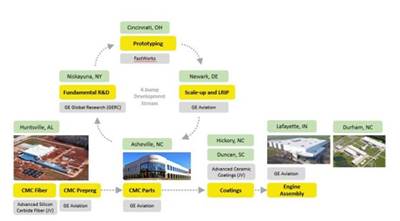
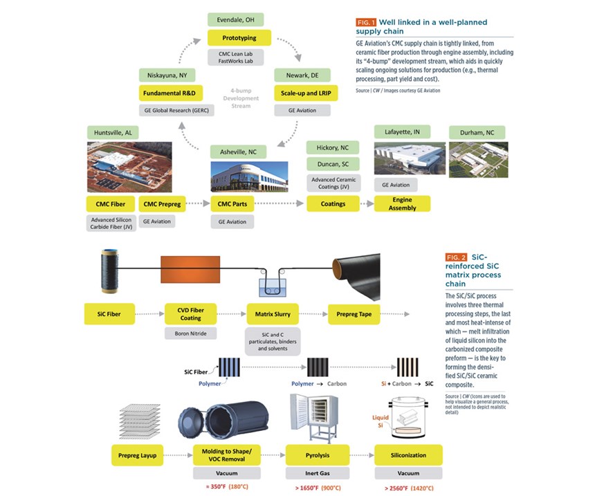
This forethought has resulted not only in a deliberate development of its supply chain structure (see Fig. 1 and Fig. 2), but also in its team-based character. “We have a tight linkage between GRC through to our Asheville production,” explains Michael Kauffman, GE Aviation’s general manager for composite and ceramics manufacturing. “This means product yield is tracked collectively through the supply chain.” Production issues also are addressed collectively, using the full breadth of GE’s CMC resources to maximize speed and efficiency (see “Vertically integrated CMC supply chain”).
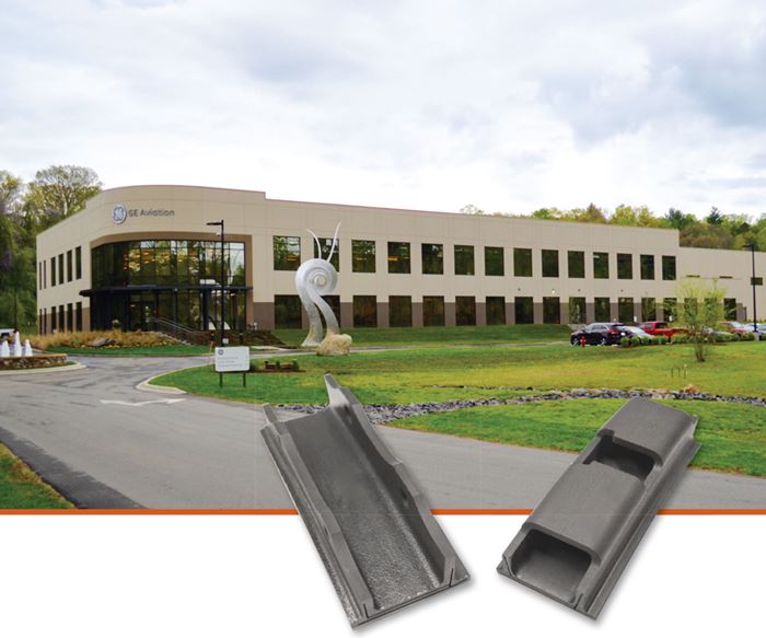
Located halfway between the CMC development lab in Evendale, OH and the CMC fiber and prepreg facilities under construction in Huntsville, AL, is GE Aviation’s new US$125 million CMC parts production facility in Asheville, NC. It is situated alongside a GE Aviation rotating parts plant that has a 70-year local history, with the most recent 25 years at this site. In May, the facility announced production of CW was invited to tour the facility and see the first-of-its-kind CMC parts production process.
Team-driven approach
CW’s tour is led by Ryan Huth, GE Aviation’s manager for CMC production. A North Carolina native, Huth has amassed significant manufacturing and engineering experience during his 12 years with GE Aviation. Well-schooled in engine certification, assembly, in the Six Sigma Tollgate process for manufacturing problem-solving and in troubleshooting engine performance issues during testing, Huth was excited to see GE choose the legacy Asheville site as the center of its CMC supply chain. “It’s not just well-situated geographically,” he explains, “it also draws from a long-established local culture of tenacious, hard-working people who rely on ingenuity and community to overcome obstacles.”
This character is a key asset in GE’s team-driven approach to achieve this plant’s objectives, which are nothing if not daunting. The facility was announced in 2013 and first opened in 2014. At completion, the full 13,000m2 plant will produce 18 high-pressure turbine (HPT) Stage 1 shrouds per engine for 500 LEAP engines yet this year. Production will ramp up to 1,100 engines in 2018 should exceed 36,000 shrouds per year for more than 2,000 engines by 2020.
LEAP production will dovetail with that for the GE9X engine, which will power the Boeing 777X when it enters service in 2020. Here, the CMC component count jumps to five, including one combustor inner liner and one outer liner per engine as well as HPT Stage 1 shrouds and nozzles and HPT Stage 2 nozzles. The number of CMC components per engine is roughly the same as for the metal components used in the previous GE90 engine. Note that high-pressure nozzles are air-flow nozzles, not fuel nozzles. The 19 fuel nozzles per engine on both the LEAP and GE9X are 3D-printed metal.
To meet this growth in production, a rapid ramp up in workforce is in progress. “We started shipping parts in 2014 with 20 employees,” Huth reports. “Every year since, we have at least doubled our employee base from the previous year.” By 2019, the facility could reach 300 employees.
Walking from the first-floor lobby to the second-floor office area, Huth points out a series of photographs mounted along the walls, taken by employees as part of an effort to show “What Asheville means to me.” He also notes that the office space, which is flooded with natural light from myriad windows, was designed to be as open as possible to encourage collaboration. Low-walled cubbies, arrayed down one side of the L-shaped area, are being filled with production and support engineers as the workforce increases. “We need chemists and ceramics engineers, mechanical engineers for the various machining processes as well as specialists in laser and ultrasonic machining processes and nondestructive testing engineers,” says Huth.
Although engineers and specialists are trained within GE before they arrive in Asheville, production technicians are hired and trained locally at Asheville-Buncombe Technical Community College (AB Tech). “We have a close relationship with AB Tech,” says Huth, “which is about 10 minutes away. They built a composites center of excellence for our employee training, complete with autoclave and cleanroom.” The training process starts with a skills assessment and behavior evaluation, followed by 40 hours of coursework at AB Tech. “From here, we invite selected candidates for an on-site interview with a panel of peers,” he adds. “If they do well, they get an employment offer and complete another 40 hours of training at AB Tech. We finish off their training here and certify them to begin work.”
The candidate behavior test and interview with potential teammates stands out. “We do not have a traditional supervisor structure here but instead have team leaders, with up to 50 people per team,” explains Huth. “This is a 100% team environment,” he adds, “our employees are high-performance and self-directed, responsible for goals, manpower coverage, problem solving and conflict resolution.” Thus, it is important that every new employee meshes well and that each team is confident in each new hire’s ability to work collaboratively. “We also cross-train everyone so that we can have as much flexibility as possible,” says Huth.
The remainder of the second floor comprises an employee gym, collaboration rooms and an outside deck for lunch meetings and breaks. “As we fill up the building with technicians and engineers, we wanted teams to have collaboration space,” says Huth, giving examples such as meetings at shift startup and for quality management and improvement (QMI) programs and “war rooms for cost-out” — GE’s shorthand for targeted cost-reduction projects.
Layup and thermal processing
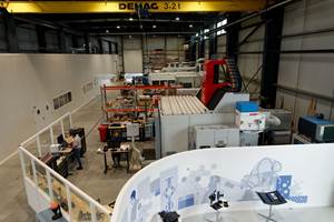
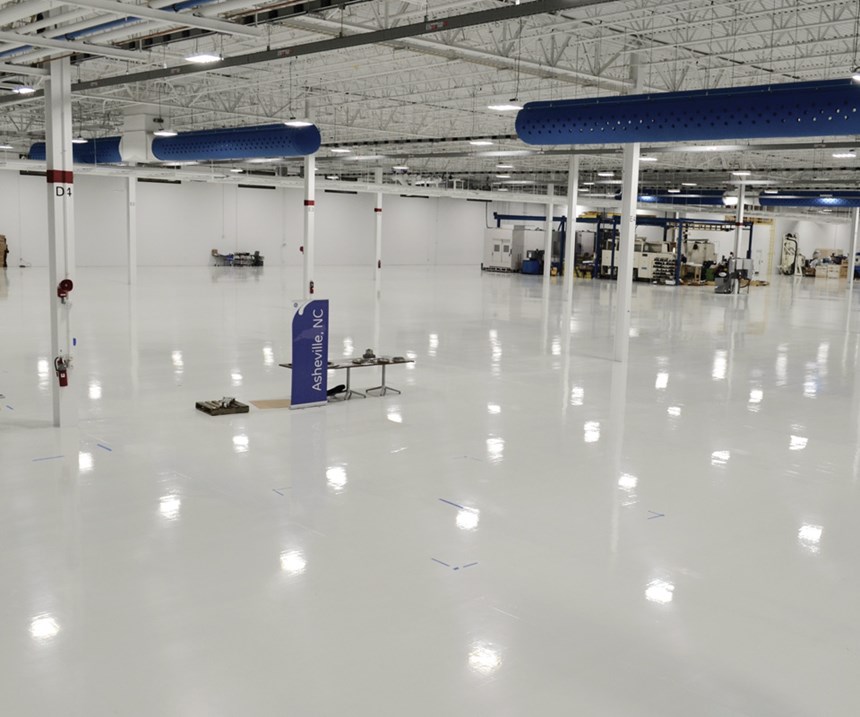
From the second floor, the tour descends back downstairs into the 13,000m2 open production area. Although the space is mostly empty, Huth says it is beginning to fill, with new additions daily. “We have a single production line right now,” he observes, “but this will be duplicated, with each line modified for the type of part being made.” He explains that the CMC technology remains the same, but the part designs differ. “This first line is making box shrouds and open shrouds for the LEAP 1A/C and LEAP 1B, respectively,” says Huth. “In the future, we will build combustor liners, blades, nozzles and other parts.”
He notes that raw material comes in from the building’s south end and eventually will feed multiple lines, forming a U-shaped production flow. Turning to where the shroud production line spans the north end of the production hall, Huth lists four basic steps in making the SiC fiber-reinforced SiC matrix composite: cutting and layup of prepreg tape, multi-stage thermal processing, post-machining of parts and nondestructive inspection (NDI).
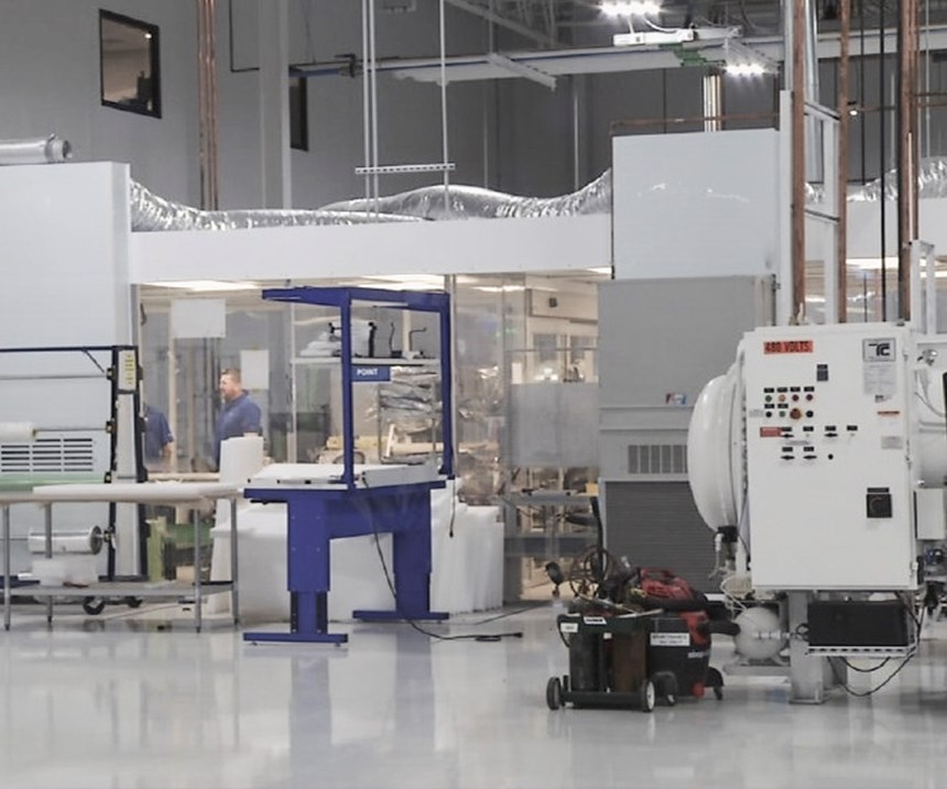
The line begins on the left, with a glass-enclosed contamination controlled cleanroom. Huth explains, “The material comes to us as a unidirectional tape and into this cleanroom, where a Gerber Technology (Tolland, CT, US) automated cutter cuts ply shapes for each part’s layup.” Today, the incoming material comes from Newark, DE. First tape from Huntsville, AL is due May 2018. The tape does not come on a roll, but in flat sheets, which are fed into the ply cutters. These plies are then laid up on a metal tool to form the composite laminate.
“Right now, layup is done by hand,” says Huth. Opposite the cleanroom is a second glassed-in layup cell, with a laser projection system supplied by Virtek Vision International Inc. (Waterloo, ON, Canada) to aid in ply orientation and placement. Both cells have computer terminals, with part drawings on the screen, and technicians are seated inside, applying the cut plies to tools. But Huth says automated layup is on the way. “The automation for this cell is being developed apart from this site and is being vetted now,” he explains. “It will be in place by fourth quarter to complement manual operations and then be scaled up, step by step, as production rate increases.”
Next is the thermal processing area, which takes up at least one-third of the production line. Thermal processing is completed in three different steps. The first step is an autoclave cycle to remove volatile organic compounds (VOCs) and mold part shape. After layup, parts are sealed underneath a reusable vacuum bag made by Torr Technologies Inc. (Auburn, WA, US). “Physics dictates our cycle time in each thermal step, so we have no ability to cut time here,” Huth explains. “We can impact door-to-door time, however, so we want all furnaces running as continuously as possible. This is why we use reusable bags.”
Efficiency also is improved by processing parts in groups of 12. Thermocouples map out lead and lag spots in the bag, and the vacuum schedule includes a reusable breather material, four thermocouple ports and two vacuum ports. The ASC Process Systems (Valencia, CA, US) autoclaves are run at temperatures typical for the higher end of polymer-matrix composites processing.
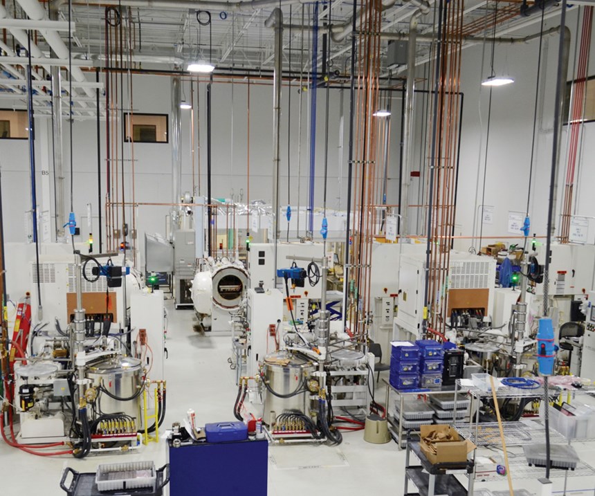
In the thermal processing cycle’s second step, “burnout” furnaces pyrolize organic material to form carbon bridges in the CMC’s microstructure. Temperatures are much higher than typical autoclave processing, and an inert gas is used. The third and final thermal step takes place in melt infiltration (MI) furnaces, which cook the parts at temperatures above their 1316°C operating temperature. They resemble metal household pressure cooker pots with clamp-on lids, albeit much larger. During MI, molten silicon is wicked through the part to react with carbon and form silicon carbide (SiC). The final product is a SiC fiber in a SiC matrix.
“We have 12 furnaces in this line,” Huth observes. “In the next few months, we will duplicate this line, adding another 12.” He notes year-over-year production increases of 900% from 2015-2016 and 400% from 2016-2017, just for LEAP engine shrouds. “We are also making parts for the GE9X.” Walking past the furnaces, Huth points out a display board for this production area that tracks Lean Manufacturing metrics. “Each team is constantly working the process for continuous improvement, and each has a facilitator who manages safety, quality, delivery, cost and cash aspects,” says Huth.
Precision machining and inspection
Huth then picks up a box shroud for the LEAP 1A/C engine. Lightweight, silver on the outer surface, white on the inner surface, it looks metallic and yet is not. He also shows a LEAP 1B open shroud, which has a little curvature. Stage 1 HPT shrouds form the annulus around the HP turbine blades. The LEAP 1B shrouds do not have the closed box on top but are open with four curved projections, which are flanges, each with a hole drilled through for attachment in the engine.
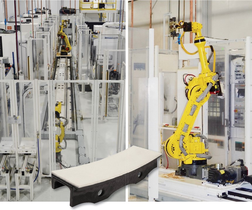
“After melt infiltration [MI], you have a fully cured CMC part,” says Huth. The next step is machining. “We use a 3R interface with vacuum chuck on each machine in the line so we can get as close as possible to single-piece flow.” This “3R” interface refers to a workpiece chucking system that enables quick setup and maximum productivity in machining lines that handle a variety of different parts. “We do simple, less-complicated machining to complete a single feature at a time,” Huth explains. “We superglue the part [workpiece] to the interface so that the robot picks it up and transfers it from station to station through the automated machining line, with no additional setup required per station. At the end, you have a fully machined and marked part.”
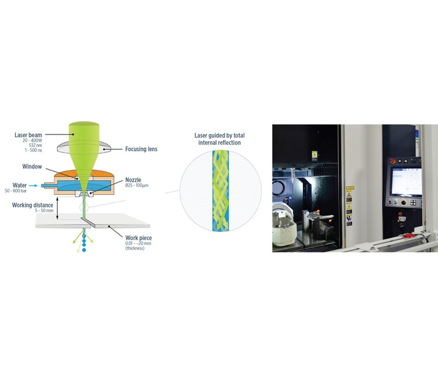
Conventional grinding on these types of parts would take an hour, according to Huth. “So we use Laser MicroJet cells which shoot the laser down a column of water.” The water cools the part and carries away debris. It also helps to maintain a high level of accuracy in the hole diameter. “The MicroJet can drill these holes in two minutes,” says Huth. The technology results from a partnership using innovative laser-cutting systems from Synova S.A. (Lausanne, Switzerland), high-precision machining technology from Makino Milling Machine (Tokyo, Japan) and GE’s fine-hole drilling software.
Shroud underside surfaces along the airflow path, which have glue dots from the 3R interface, are machined smooth using diamond abrasives. But Huth notes this is the subject of an ongoing cost-out project, “We won’t be doing this for long.”
The final step in the CMC part production line is NDI using computed tomography (CT) machines from GE. Every part is inspected with an approximate scan time of 15 minutes, followed by another 30 minutes for completion, including data evaluation.
Big picture and Big Data
The pace in Asheville is fast, but not frenzied. GE has thought out all things necessary not only to deliver parts for engines already ordered, but also to ensure this facility remains at the forefront of production for the next 70 years. A case in point for the long-term is the network of silver tubes that runs from each machine in the plant up to the ceiling. “These house Ethernet cables, all tied to our database system,” says Huth. “So layup times, relative humidity in clean rooms, furnace cycles, machining metrics and CT scans are all logged for each part’s digital thread, and also for analysis to help us refine processes, both for speed and cost reduction.”
Kauffman says GE’s Big Data capability is a cornerstone of its CMC supply chain strategy. “Big Data is key for our CMC supply chain because it is highly process-sensitive, and there are thousands of input variables with continuous variations,” he explains. “The beginning elements in fiber spinning affect not only fiber coating and prepregging, but all the way to how consolidation occurs in the components.” The collection and integration of Big Data throughout the supply chain also directs product and process simulation models. “We let the data find its correlations,” says Kauffman, “and it often finds things we, frankly, didn’t predict in our models.”
Why commit so much to the design and establishment of this supply chain? “Because we have invested a great deal of money over the last decades and this CMC technology is a differentiator for our products,” Kauffman replies. “We want to protect this investment and our intellectual property. We are familiar with what our competitors are doing, and we are the only ones to use this approach to infiltration of a reinforcement, which we believe achieves better densification.” He notes that another driver was to make sure GE’s partners were willing to industrialize CMCs as well. “Industry’s commitment to CMCs has been off and on,” says Kauffman, “but we believed there was too much to gain in weight reduction, performance and efficiency — for us, the decision was clear.” And now, so is the path forward.
Related Content
Plant tour: Spirit AeroSystems, Belfast, Northern Ireland, U.K.
Purpose-built facility employs resin transfer infusion (RTI) and assembly technology to manufacture today’s composite A220 wings, and prepares for future new programs and production ramp-ups.
Read MorePlant tour: Airbus, Illescas, Spain
Airbus’ Illescas facility, featuring highly automated composites processes for the A350 lower wing cover and one-piece Section 19 fuselage barrels, works toward production ramp-ups and next-generation aircraft.
Read MorePlant tour: Daher Shap’in TechCenter and composites production plant, Saint-Aignan-de-Grandlieu, France
Co-located R&D and production advance OOA thermosets, thermoplastics, welding, recycling and digital technologies for faster processing and certification of lighter, more sustainable composites.
Read MorePlant tour: Arris Composites, Berkeley, Calif., U.S.
The creator of Additive Molding is leveraging automation and thermoplastics to provide high-volume, high-quality, sustainable composites manufacturing services.
Read MoreRead Next
Vertically integrated CMC supply chain
GE Aviation's new ceramic matrix composite supply chain includes fiber, prepreg and unprecedented parts production facilities, plus a strongly tied 4-bump development stream.
Read MorePlant tour: Daher Shap’in TechCenter and composites production plant, Saint-Aignan-de-Grandlieu, France
Co-located R&D and production advance OOA thermosets, thermoplastics, welding, recycling and digital technologies for faster processing and certification of lighter, more sustainable composites.
Read MoreAll-recycled, needle-punched nonwoven CFRP slashes carbon footprint of Formula 2 seat
Dallara and Tenowo collaborate to produce a race-ready Formula 2 seat using recycled carbon fiber, reducing CO2 emissions by 97.5% compared to virgin materials.
Read More



.jpg;maxWidth=300;quality=90)

