
The basics of composite drawing interpretation
Knowing the fundamentals for reading drawings — including master ply tables, ply definition diagrams and more — lays a foundation for proper composite design evaluation.


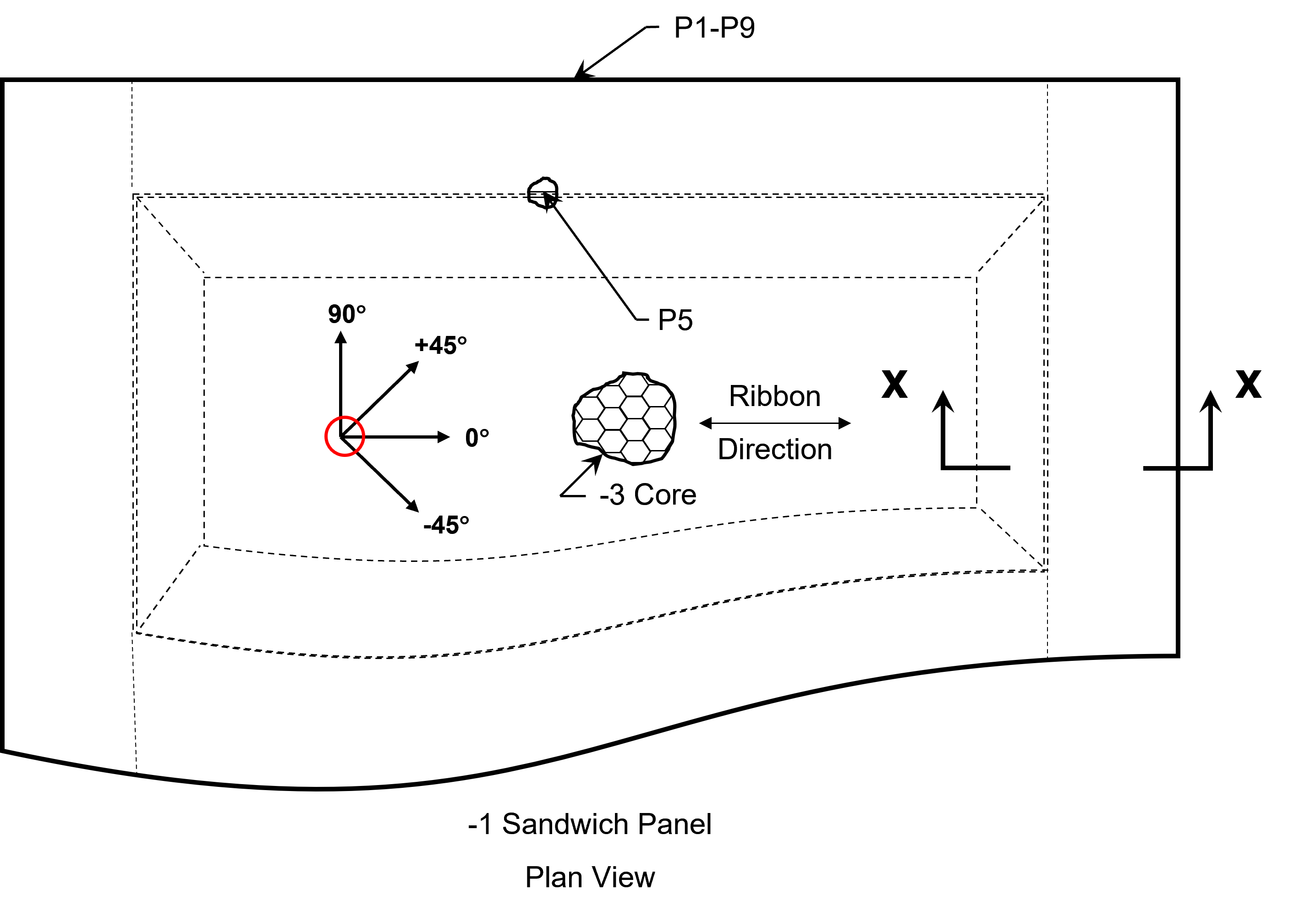
Figure 1. The fiber orientation is controlled and can be inspected at the exact point where it is shown in the plan view of the part laminate drawing. A red circle on this illustration denotes the intersection where this is applicable. Also note the core callout on the plan view. Photo Credit, all images: Abaris Training Resources Inc.
Fiber orientation is critical to the performance of any fiber-reinforced polymer (FRP) laminate, especially those used in aerospace structures. Designers carefully choose the fiber type, fiber form (unidirectional, bidirectional, multiaxial, braided, etc.), and primary fiber axial orientation of each ply that goes into the design. The ply orientation requirements are designated on the part drawing using a common system of drawing views, ply tables and orientation symbols. Flag notes are used in the ply table to call out the materials, splice overlaps, fiber orientation tolerances and more. In this article, we clarify how this information is commonly disseminated and understood, to assist those who are tasked with interpreting composite drawings.
First, let’s look at the orientation symbol on the drawing, what it represents and how it is applicable to the laminate structure (Fig. 1). Typically, the 0° axis of the symbol designates the primary load direction of the laminate or the global structure. The ISO standard counterclockwise orientation symbol (or some version of it) is found on the plan view of the part — looking at the backside of the laminate, from the layup operator’s perspective, the symbol is located exactly where the fiber orientation is controlled and should be inspected on the laminate. It is of great importance to control the fiber axes at this single location, as the fiber directions can change significantly over a contoured shape. This is taken into consideration at the design level to ensure that fiber axial loads are realized throughout the structure. When the panel is a honeycomb sandwich structure, the core will be shown in a cutout section, adjacent to a local callout for the core ribbon direction.


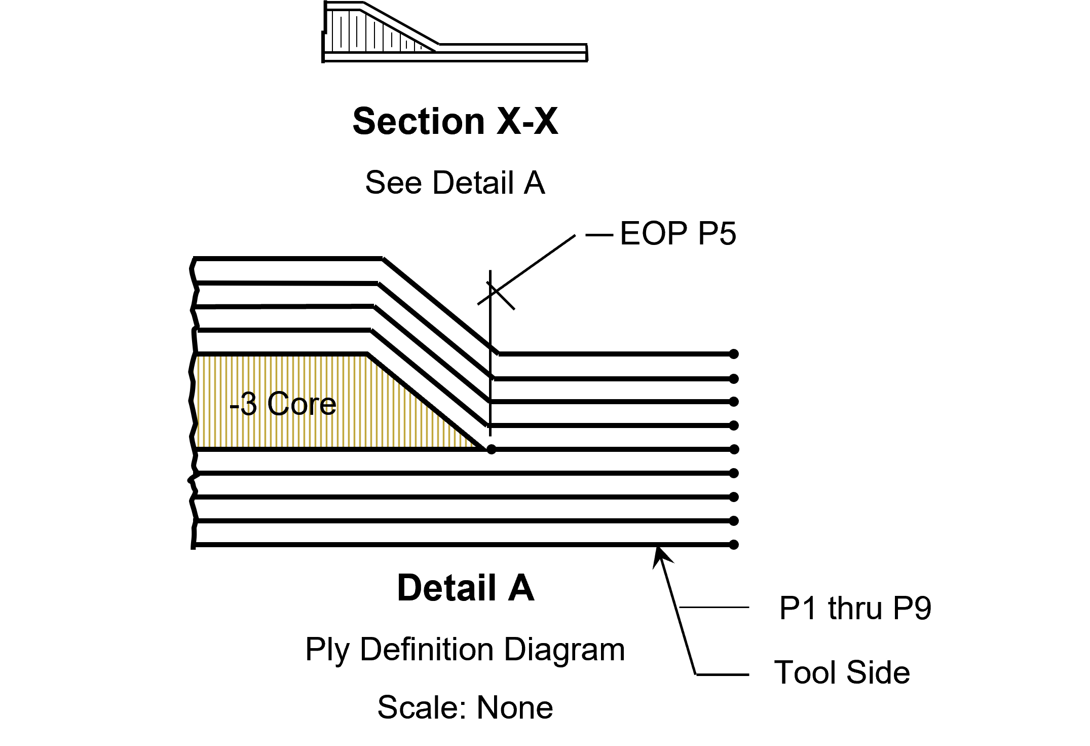
Figure 2. The ply definition diagram provides ply location information to manufacturing.
The laminate construction is further depicted using a ply definition diagram (PDD) that is shown in a detail view related to the cross-section(s) taken from the plan view. The designer provides as many section views and PDDs as required to clearly identify and locate each ply, adhesive layer and component in the laminate stack (Fig. 2). This method enables instant communication of the plies/layers that exist at each section.
A master ply table is usually found on the same drawing sheet as the plan view and includes every ply, adhesive layer, component, etc. that is included in the part laminate. The ply table will always have the ply numbers, orientation and material information (Fig. 3) but may also include columns that designate part (dash) numbers, engineering sequence information, ply splice requirements and more — whatever is necessary to define the layup. Some designers may also use mini localized ply tables adjacent to each ply definition diagram for further clarification of complex layups. The information in the mini tables will always match up with that of the master ply table.
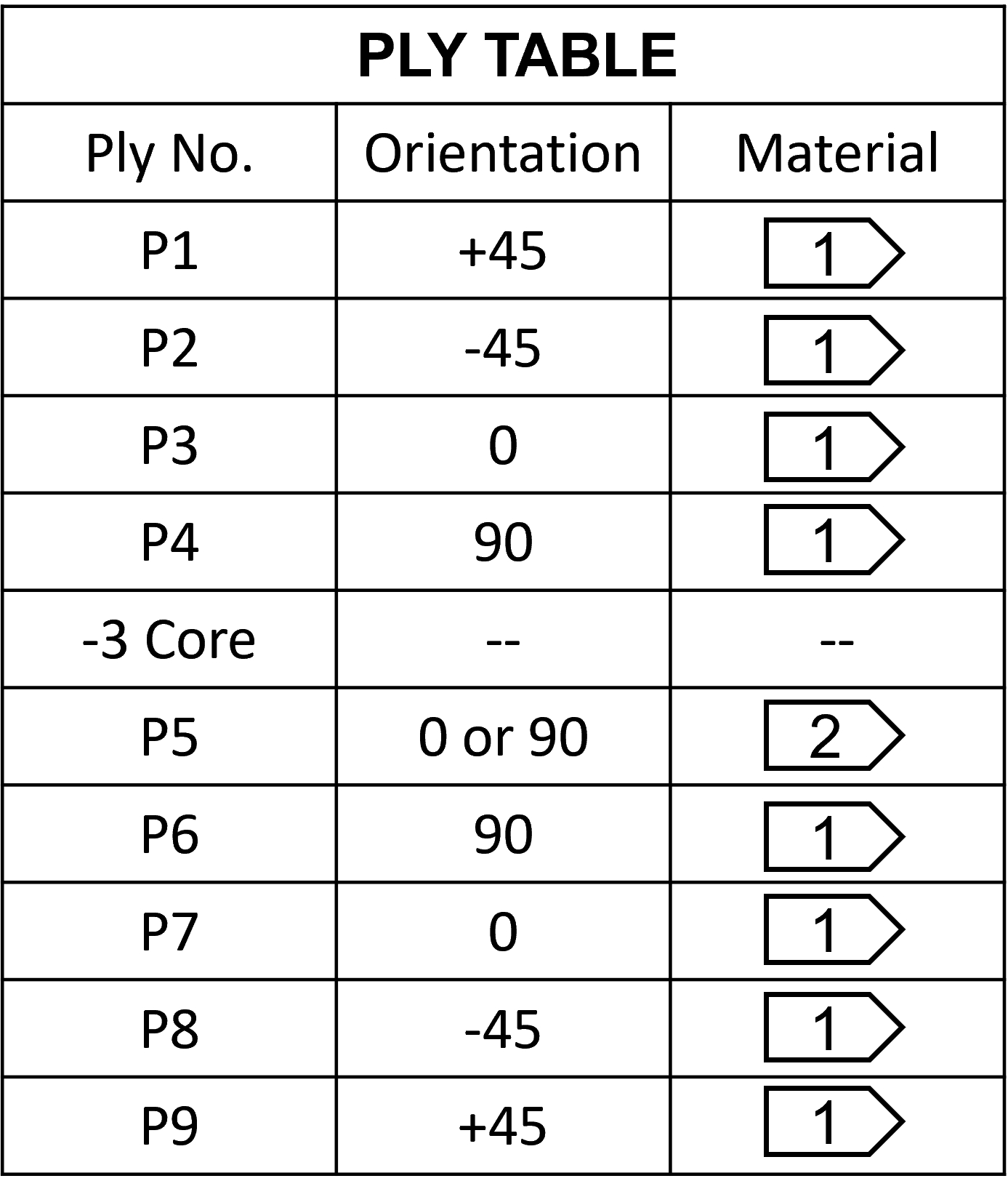
Figure 3. The ply table is used to communicate laminate construction information.
Design engineers create a full-size, unwrapped, flat pattern layout of each ply/layer so that this information can be used to cut the materials needed for layup. Full-size digital files can be sent to an automated ply cutter system or used to make ply templates. A smaller scaled version of the flat pattern layout is often found on its own sheet of the drawing. This can be extremely useful in determining the ply/layer configuration and layup sequence (Fig. 4).
Each drawing has a parts list and notes list. These are either found on the first sheet of the drawing or in a separate document that is part of the overall drawing package. The parts list will include all parts (dash numbers) that are applicable, and the notes will provide all other relevant information.
There are two types of notes to be aware of — the general notes that apply to all elements of the drawing, and the flag notes that are specific to wherever the flags are shown on the field of the drawing or in the ply table(s). The ply orientation tolerances are called out in the general notes (not in the drawing tolerance block) and apply where the orientation symbol is located on the plan view. (Yes, I said it again — it is that important!) All other materials used in layup are called out in flag notes. Flag notes are designated as such, either inside a flag-shaped symbol as seen in the ply table (3), or by other means described in the notes list.
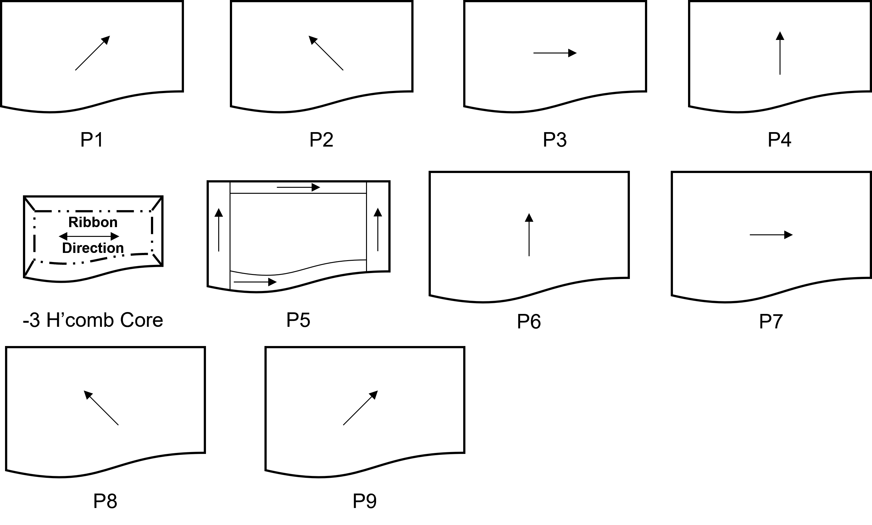
Figure 4. A flat pattern layout scheme provides the reader with instant recognition of layup details.
The following is a list of steps for “reading” a composite part drawing:
- Read the title block for the part description (title), drawing number, revision level and other identifying information.
- Survey the plan view, side view and section/PDD views to get a sense of the laminate construction, overall dimensions and where the flag notes appear on the field of the drawing.
- Note the location of the orientation symbol and core ribbon direction callout (if applicable) as shown in the plan view.
- Review the master ply table and the flat pattern layout.
- Read the entire parts list and all of the notes, paying special attention to the material callouts, specifications and special instructions found in the flag notes.
- Continue to repeat these steps as needed until the layup is well understood.
While this column covers many of the fundamentals, it should be noted that specific drawing practices can vary from one manufacturer to another. You might find different flag note symbols, ply numbering designations or other minor variations in how the plies are drawn in the PDDs. If you work for a Tier supplier to multiple companies, or a small company doing build-to-print business, you may have several different drawing methods to deal with. It is suggested that you look for the commonalities between the drawings — after all, they are all communicating the same type of information.


.jpg;maxWidth=300;quality=90;format=webp)
Related Content

Composite sidewall cover expands options for fire-safe rail components
R&D project by CG Rail explores use of carbon fiber-reinforced thermoplastics and recycled manufacturing scrap to meet fire safety, weight and volume targets.
Read More
Aurora reveals latest SPRINT X-Plane design concept
An Aurora and Boeing team advances its high-speed, vertical lift concept to the preliminary design phase, which features three lift fans, a more refined composite exterior and an uncrewed cockpit.
Read More
ASCEND program update: Designing next-gen, high-rate auto and aerospace composites
GKN Aerospace, McLaren Automotive and U.K.-based partners share goals and progress aiming at high-rate, Industry 4.0-enabled, sustainable materials and processes.
Read More
Nine factors to consider when designing composites cure tooling
Gary Bond discusses the common pitfalls and compromises when designing good cure tooling and their holistic significance for a robust composite production process.
Read MoreRead Next

Doing the twist: A look at dimensional issues in high-temperature cured laminates
When it’s not the tooling, the root cause of dimensionally inaccurate composite parts often boils down to two things: fiber form(s) used and laminate symmetry.
Read More
VIDEO: High-volume processing for fiberglass components
Cannon Ergos, a company specializing in high-ton presses and equipment for composites fabrication and plastics processing, displayed automotive and industrial components at CAMX 2024.
Read More
All-recycled, needle-punched nonwoven CFRP slashes carbon footprint of Formula 2 seat
Dallara and Tenowo collaborate to produce a race-ready Formula 2 seat using recycled carbon fiber, reducing CO2 emissions by 97.5% compared to virgin materials.
Read More