Proving thermoplastic composites match carbon fiber/epoxy performance in road bikes
CDCQ, LxSim, Addcomp and Argon 18 collaborate to optimize a carbon fiber/PA6 bike seat post, democratizing AFP and demonstrating materials and process for future designs and production.
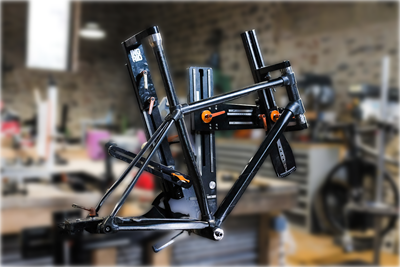
Thermoplastic composites (TPC) are at the forefront of the revolution in materials and processes for the cycling industry, says Vincent Lemay, VP of R&D for Argon 18, a high-quality bike manufacturer in Montreal, Canada. “I think the industry will go this way in the near future, because these materials enable quick, efficient and less labor-intensive processes [see CW’s 2022 feature on bike frames]. But in the cycling industry, we have very detailed, tailored layups, which is why they are done manually right now.”
These layups are also almost exclusively thermoset composites, notes Lemay, using carbon fiber-reinforced polymer (CFRP) based on epoxy prepreg for road racing models, where lightweight performance is paramount. “This is what we wanted to address,” he explains. “How can we develop comparable carbon fiber (CF) layups with thermoplastics yet retain the high performance of traditional epoxy-based CFRP?”
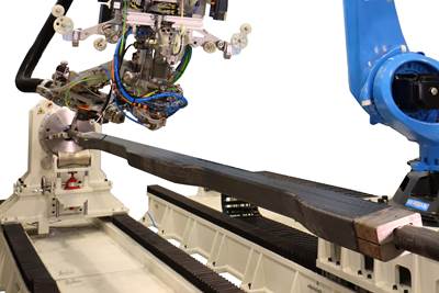
To answer this, Argon 18 worked with the Quebec Composites Development Centre (CDCQ, Saint-Jerome, Canada) and engineering simulation specialist LxSim (Bromont, Canada), as well as composites automation company Addcomp (Sherbrooke, Canada) to evaluate six different TPC materials. It developed an optimized layup for 2D blanks which were made using automated fiber placement (AFP), shaped onto a mandrel and then compression molded using a bladder-based process to produce and test two of these materials in a bike seat post demonstrator.
Project partners and objectives
The project began with Addcomp’s installation of a customized robotic AFP cell at CDCQ. “We were looking at different projects to demonstrate what this cell could do,” explains Yoann Bonnefon, CEO of Addcomp. “We were already working with CDCQ to evaluate different TPC materials and also wanted to collaborate with LxSim due to their expertise in composites optimization.”
Argon18 was also interested in testing various TPC materials. “CDCQ is a longstanding partner helping us explore how to produce more efficient, lighter and safer bicycles,” says Lemay. His team suggested the bike seat post as a basis for comparison. The project began with material characterization and selection, followed by fabrication and testing of the demonstrators.
Six different carbon fiber-reinforced thermoplastic composite (TPC) tape materials were tested using automated fiber placement (AFP) to make plaques for coupons.
“We started in 2023, and performed the materials testing in our lab,” says Yves Mathieu, project manager at CDCQ. “Our initial tests were on flat coupons made using robotic AFP layup with different angles and then hot press molded into plaques.” The team tested six different unidirectional (UD) tape materials made using standard modulus CF with various thermoplastic polymers — including Rilsan polyamide11 (PA11), polypropylene (PP), Maezio and Gordon Plastics polycarbonate (PC), Toray TC910 with polyamide 6 (PA6) and PA12 tape from Suprem — and compared their properties to the baseline CF/epoxy material, selecting two TPC materials to use for the demonstrator parts.
LxSim used the initial property data for those two TPC materials in its finite element analysis (FEA) design and optimization of the demonstrator, aiming for parity with baseline CF/epoxy parts. “We then used the robot cell to lay up optimized 2D blanks and used a bladder molding process to convert those into hollow bike seat posts,” says Mathieu. “These demonstrators were then tested by Argon 18.”
“We chose a seat post because it’s a simple shape,” explains Lemay. “But because it attaches the saddle [seat] to the bike frame, it has quite a complex load case that we can simulate. Our initial goal as a bike manufacturer was to characterize and compare the TPC materials and then use that data to feed our FEA simulations to compare with existing CF/epoxy parts. But we also wanted to optimize the layup for the seat post and develop the manufacturing process at the same time. These are the biggest roadblocks for us to start using TPC: how to optimize and produce the parts efficiently. If we can simulate the failure mode accurately, we can then optimize our part using FEA and from there the layup for larger and more complex parts.”
Materials testing, process development
Material properties tests were performed for six TPC materials using plaques made using AFP layups (A) placed into matched aluminum mold sets (B) that were then consolidated in a heated press (C) and waterjet cut into various ASTM coupons (D).
“We programmed the robot to apply the PA6 and PC composite tapes,” says Mathieu, “which was a bit tricky because they were not the same areal weight as the CF/epoxy that we were used to. So, we needed to tweak it to achieve the prescribed layups. The fiber areal weight of the TPC tapes was defined by the material supplier, and though we targeted 150 gsm, some materials were 131 gsm.”
“Our main selection parameters were stiffness and low density,” adds Mathieu. “But there are limitations from the heating system in the AFP process — for example, our system uses hot air. So, we also compared materials in terms of processability and price to make our selection.”
The AFP layups were then placed into two-part aluminum molds and consolidated in a Carver (Wabash, Ind., U.S.) 100-ton heated press. Molding time was 5 minutes once melt temperature was reached. Test coupons were waterjet cut from various plates made to fully characterize the two selected materials per ASTM specifications for flexural, tensile, compressive and in-plane shear properties.
The two UD tape materials Argon 18 chose to make the bike post demonstrators were a CF/PA6 from Toray Advanced Composites (Morgan Hill, Calif., U.S.) and a CF/PC from then Gordon Plastics (Englewood, Col., U.S.), acquired by Toray in November 2024. Lemay notes that low-melt polyaryletherketone (LMPAEK) polymer (Victrex, Lancashire, U.K.), and other high-performance TPC materials used in aircraft, were not considered due to cost. “We thought we could optimize a CF/PA6 layup to be as performant as the current CF/epoxy we use, and this was the goal of the project ”
Another objective was to develop the process. “To make the whole part from TPC was a big challenge,” says Eric Allard, mechanical engineer for composites development at LxSim. “I come from the ice hockey industry, and we tried to do this in the past. But it’s not easy to create an optimized preform and then keep the fibers straight as you mold the part.”
He explains this is because TPC materials are rigid at room temperature. They must be heated to melt temperature as they are applied to create a multidirectional stacked laminate and then molded into a final part. “We developed a process that uses AFP to create the laminate and then we rolled that preform around a mandrel to form a shaped preform which was then bladder molded. There were also challenges with bladder materials because the TPC molding temperature is higher than with CF/epoxy.
AFP layups were applied onto Thermalide polyimide release film (left) and glass fiber fabric (right).
Another issue was finding a high-temperature release layer for the first ply during AFP. The team used Thermalide (Airtech, Huntington Beach, Calif., U.S.), a polyimide release film for temperatures up to 405°C, and an 8-harness satin glass fiber fabric from BFG Industries (Danville, Va., U.S., a subsidiary of Porcher).
“It was a good learning experience for all of us,” adds Mathieu, “to go from the raw tapes to the 2D engineered blank rolled into cylindrical-shaped preforms and then final molding of the hollow seat post. We worked a long way up the learning curve and matured the process to get good compaction and control of the fiber angles and gaps.”
Simulation to optimize the part
With initial testing and material selection completed, LxSim began to optimize the layup and part for producing the final demonstrators. “We had developed the FEA model of the seat post,” says Allard, noting the post is typically round and inserted at an angle between the bike frame and saddle/seat. “We defined the boundary conditions and the key load cases and then we virtually tested the part in FEA, loading it vertically from the seat, but replicating the offset, which results in bending and compression on the post.”
“There’s also a clamping on the frame,” adds Lemay, “which creates a highly compressed area. That’s why this post was a great demonstrator, because it included a lot of the failure modes that we can see on a bicycle component.” Both LxSim and Argon 18 used Hyperworks (FEA model) and Optistruct (solver) simulation software from Altair Engineering (Troy, Mich., U.S.).
“We had the reference layup for the CF/epoxy seat posts, so we had their stiffness and weight,” says Allard. “And those were our targets for developing the new layups, considering the stiffness-to-weight ratio of the CF/PA6 and CF/PC materials.” He notes there were some drawbacks with the PA6 and PC material stiffness not being as high as the CF/epoxy. “However, we could match this performance including fatigue loading by optimizing the TPC layup. But we needed to make sure we wouldn’t get other failure modes.”
LxSim came up with two different layups similar in stiffness and weight. “We used a total of 14-16 plies depending on whether it was PA6 or PC,” says Allard. “And the reference part in CF/epoxy was 20 plies.” Although the laminate was not quasi-isotropic, it did have fiber orientations starting at 0° and rotating at 15° increments. “So, we could tune the fiber angles, and though it’s possible to do fiber steering with TPC tape, we didn’t try it in this project.”
These layups were then used by CDCQ to optimize the process. “Working with the team at CDCQ, we developed a way to translate the optimized layups to an AFP-produced laminate,” says Allard. “We had to make a prototype to get correlation between the FEA and the actual layup. We then had to make some adjustments.”
“The PA6 laminate was right on target,” he continues, “but the PC laminate needed iteration. That shows why it’s good to do the material characterization in the beginning to feed the FEA — it reduces the trial and error and development time to achieve all the targets. Those flat panels were then formed via a rolling process over a mandrel to make the preform that was bladder molded into the final part. So, the whole process started from a flat laminate with staggered plies.”
FEA simulation was also used to investigate failure at the ends of plies (above) and optimize staggering of plies to form the round tube.
Why staggered plies? “We needed a kind of step joint where the flat panel met itself to form the tube,” explains Allard. “And those had to be distributed around the tube. When we rolled these plies to make the tube, we needed to see if we would get any failure at the ends of the plies or any defect in the shape. In the end, it worked fine.”
Manufacturing the demonstrators
Seat posts were made by wrapping a 2D preform around a Mosite1453 silicone bladder (left) and placing into a matched metal mold and heated press. The gap between the preform and mold (red arrows top right) must be near zero for good material compaction, illustrated in the cross section at bottom.
It took 20 trials to reach an acceptable part, during which a variety of issues were addressed, including bladder leaks, mandrel sizing and the rolling procedure for applying plies to the mandrel. “That was not as straightforward as with CF/epoxy prepreg, where the laminate is applied onto the mandrel ply by ply,” notes Mathieu. “With TPC, you have a semi-consolidated layup, so the rollup process is not as tight because the plies are all there already and the TPC tape is more rigid, even when heated. So, we had to go more slowly and really work with the material.” In the end, the team was able to make a part with the designed dimensions, achieving good compaction while minimizing voids.
Mathieu points out that for the tooling, CDCQ worked with a partner R&D center, St. Clair College (Windsor, Canada). “The tool was partially designed and machined by mechanical engineering students who also helped out in the manufacturing of the tubes as part of their composites training program,” he says.
A bracket compression molded from tape scraps (left) was also fused to the bike seat post (right) in a kind of welding/fusion process.
After bladder molding, CDCQ also trialed fusion welding a bracket onto the seat post, which went relatively well, says Mathieu. “After we consolidated the tube in the bladder mold, we had a different tool we put on the end of the seat post and into which we placed a bracket made from compression molded tape scraps. We then closed the tooling and heated in the press so that we basically co-melted and fused the two parts together.”
“This small bracket connects the saddle to the post,” adds Lemay, noting that such features on bike frames are mostly compression molded using thermoset composites. “So, it was good for us to demonstrate it with TPC. Normally, it’s a solid part that comprises a complex layup of small pieces and stacks of plies, but we used the leftover pieces of TPC tape from the AFP process, which could enable a closed loop recycling process in-house.”
On par with epoxy, future developments
Clamping tests (left) as well as static load tests (right) and rigidity tests were performed on the demonstrator bike seat posts.
After producing the demonstrator seat posts, Argon 18 tested them on its in-house test bench. This included clamping tests where the seat post must withstand 200% of the 4 newton-meter clamping torque. Demonstrators from both the CF/PA6 and CF/PC materials passed, but the maximum clamping torque was 19% higher for the latter.
Next, fatigue performance was tested, applying 100,000 cycles of a 1,200-newton vertical load. In this test, the TC910 CF/PA6 seat post passed while the Gordon 40-150 CF/PC post narrowly failed, perhaps to a processing imperfection. Unfortunately, this post could not be included in the subsequent static load tests, where a maximum load of 2,000 newtons was applied for one minute at an offset of 70 millimeters. The TC910 tube passed. However, both posts passed rigidity tests, with results within 8% of the reference CF/epoxy seat post.
“The results showed that it is possible for us to produce a TPC part that’s as good as our current CF/epoxy parts,” says Lemay. Argon 18 will also test the TPC demonstrator seat posts on an instrumented bike to characterize their stiffness and comfort for the rider in real-life conditions. “We’ll use this to characterize the vibration absorption, which is one of the key advantages of TPC compared to thermoset composites for bike frames. By early 2025, we’ll be able to compare this performance to our current CF/epoxy, in different types of cycling conditions.”
He thinks that eventually, even high-end road racing bikes will be manufactured using TPC, and maybe even using a more costlier resin system, “but the roadblocks are how to easily fine-tune the plybook to achieve the performance we want. For Argon 18, we won’t target the high-end products at first, but instead at the mid-range. From our initial simulations, I think it’s possible there to achieve the same performance at the same price point, but there’s still a lot of work to do before we could put this into production.”
Even though current Argon 18 road bikes are based on thermoset CFRP, the company sees a future for TPC parts like the demonstrator seat post shown here.
“We do see a big shift coming in the cycling industry,” says Lemay. “Everything is geared right now to use thermoset composites, but we’ve seen companies start to use TPC in mountain bikes and Rein4ced is also working with it in road bikes. But there are also significant challenges in developing the manufacturing processes. You can’t just go and buy the equipment off-the-shelf. It’s not there yet. So, we need to develop the recipe and the equipment according to what we need, and that’s why this type of project was so valuable — to collaborate with the CDCQ’s technological center, LxSim’s simulation expertise and Addcomp’s industrial expertise was a win-win for all of us.”
For Addcomp, this project proved that innovative systems like AFP can be democratized to industries like sports and leisure and also to smaller companies, says Bonnefon. “It was a great demonstrator for the affordable, customized robotic cells that are now available, which can enable companies like Argon 18 to use more advanced and automated composite technologies.”
And will Argon 18 continue forward with this development? “We achieved our initial goals and now we’re working to further refine the process,” says Lemay. “We have a separate project working on more advanced thermoforming and to see where we can push the layup optimization for even further performance.”
Related Content
Plant tour: Joby Aviation, Marina, Calif., U.S.
As the advanced air mobility market begins to take shape, market leader Joby Aviation works to industrialize composites manufacturing for its first-generation, composites-intensive, all-electric air taxi.
Read MoreOptimizing a thermoplastic composite helicopter door hinge
9T Labs used Additive Fusion Technology to iterate CFRTP designs, fully exploit continuous fiber printing and outperform stainless steel and black metal designs in failure load and weight.
Read MoreCombining multifunctional thermoplastic composites, additive manufacturing for next-gen airframe structures
The DOMMINIO project combines AFP with 3D printed gyroid cores, embedded SHM sensors and smart materials for induction-driven disassembly of parts at end of life.
Read MoreDeveloping repairs for thermoplastic composite aerostructures
HyPatchRepair project proves feasibility of automated process chain for welded thermoplastic composite patch repairs.
Read MoreRead Next
MFFD thermoplastic floor beams — OOA consolidation for next-gen TPC aerostructures
GKN Fokker and Mikrosam develop AFP for the Multifunctional Fuselage Demonstrator’s floor beams and OOA consolidation of 6-meter spars for TPC rudders, elevators and tails.
Read MoreThermoplastic composite, tube-shaped preforms for large-volume manufacturing
Starting with the sporting goods and bicycle market, French startup 3DiTex targets its continuous preforming system for thermoformable, thermoplastic composite tubes in complex geometries.
Read MorePlant tour: Arris Composites, Berkeley, Calif., U.S.
The creator of Additive Molding is leveraging automation and thermoplastics to provide high-volume, high-quality, sustainable composites manufacturing services.
Read More

