Composite repair: Lessons learned, challenges and opportunities, Part I
As aerospace companies look to increase the scope and quality of repairs, through standardized training and increased automation, their lessons learned (outlined here in Part 1 of a two-part examination) can smooth the repair path for other industries.
Over three decades, the aerospace industry has collaborated successfully to produce standard composite repair designs, materials and methods and foster confidence in the ability to repair composite structure. As aerospace companies look to increase the scope and quality of repairs, through standardized training and increased automation, their lessons learned (outlined here in Part 1 of a two-part examination) can smooth the repair path for other industries. The opportunity to avoid costly repair issues, however, could be missed if the OEMs and owner/operators in these industries resist collaboration and the resulting standards and technology necessary for an effective repair supply chain.
From bolted doublers to bonded repair.
At Lear Fan Ltd. in the early 1980s, the common repair method for composite structures was bolted doubler repair, because this was the way metal struc- tures were repaired. Applying CFRP doublers to CFRP structures, we quickly learned that the common aluminum alloy fasteners experienced galvanic corrosion in contact with carbon fiber. So we switched to stainless steel, and later, titanium fasteners.
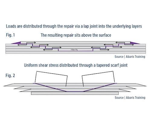
The bonded patch step repair followed soon thereafter, which was the standard approach used for a multi-layered metal structure. The damaged material from each layer was removed in progressively larger diameters, creating a stepped surface in which to replace plies (Fig. 1, at left). For composites, this posed serious challenges. The first was to remove the damaged material down to the undamaged layer without intruding into that ply, which would make the repair larger, and require more time, labor and risk to return the structure to acceptable performance. The second was to actually make repair plies fit into each stepped recess without overlap or gaps — an extremely difficult, operator-dependent task.
The transition from step repairs to tapered scarf repairs began around 1984-1987. These were easier to perform and provided better results. Boeing specified them in its aircraft structural repair manuals (SRMs). Without the steps, you no longer had to worry if you were 1.0 mm off in the repair ply location (Fig. 2).
However, companies making general aviation (GA) aircraft and Airbus were still prescribing step repairs, or alternately, upside-down “wedding cake” taper-scarf repair patches — i.e., the largest diameter ply at the bottom and smallest at the top, covered by a final layer that seals the repaired area. This technique came from the marine industry, which typically used heavy woven roving, where the thick exposed edges were easily accessed later for removal of trapped air and ease of finishing. The approach became unnecessary in the aerospace industry, when thin harness-satin and plain-weave fabrics were used, vacuum bagging was employed for compaction and gas removal, and portable hot bonder equipment monitored and logged repair patch vacuum and cure temperatures. Through the 1990s, the “big ply down” vs.“little ply down” debate continued. Airlines and repair-station tech- nicians were frustrated with the inconsistency in repair methods, and sought simple, efficient techniques. (Note: the big-ply-down method is still employed in some GA repair schemes.)
Bonded and bolted doublers on thin-skin laminates also were prescribed. However, in the early days, there weren’t a lot of fasteners specifically developed for composites, and it was common for wear around the holes to cause fastener pull-out failure. Huck (now Alcoa) and others eventually introduced now common fasteners with larger heads, which dramatically improved performance. Bolted doublers have been used on thick laminates since the 1980s and are often used in non-aerodynamic, flight- critical areas today. The common rule of thumb is to use bolted doublers on thick laminates (>13 mm) and bonded, tapered scarf repair on thin laminates (<3.2 mm), with sufficient analysis to substantiate the appropriate repair design.
Automation, training and increasing allowable bonded repair limits.
Since the 1990s, taper-scarfed repairs have become the method of choice on thin laminate structures, using the small-ply-down-first approach, ensuring a flush overall final ply for an aerodynamic surface. The focus now is on developing standardized repair technician training and adapting repair patch preparation methods, including double vacuum debulk (DVD) processing and automation to extend bonded repairs to increasingly larger areas of damage and flight-critical primary structures (see endnote). The goal is reduced human error and increased precision in nondestructive inspection, damage removal, adhesive bond preparation and repair patch application and cure.
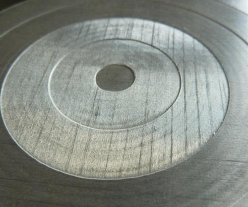
Today’s robotic systems can, indeed, CNC mill each damaged ply from the digitally scanned and verified repair area with preci- sion. Some systems, such as mobileBLOCK from DGM Mori (Bielefeld, Germany) can mill both step and taper scarf surfaces (Fig. 3). However, many of these automated systems still create a stepped repair area, which ironically brings back the old issue of matching the repair plies — although more precision is possible with digital ply cutting capabilities — because repair patch application is typically still done manually. Obviously, the next objective is to automate the patch application and cure.
The increased standardization in requirements for repair technicians and their training has largely been the result of collaboration through the Commercial Aircraft Composite Repair Committee (CACRC), which is administered by SAE International (Warrendale, PA, US), with technician certification provided through the Performance Review Institute (PRI). This group, along with OEMs, operators, suppliers and service providers, has provided a forum for discussion, research and dissemination of repair knowledge (and archiving), and serves as a model for development in other areas.
In Part II, Dorworth will discuss how the automotive and wind energy industries can and are benefitting from aerosapce industry experience. He also will treat this topic in detail at CompositesWorld’s Carbon Fiber 2016 conference (Nov. 9-11, Scottsdale, AZ, US)
Related Content
Park Aerospace launches aerospace, MRO structural film adhesive
Aeroadhere FAE-350-1 is a curing epoxy formulation designed for composite, metal, honeycomb and hybrid applications.
Read MoreFilm adhesive enables high-temperature bonding
CAMX 2024: Aeroadhere FAE-350-1, Park Aerospace’s curing modified epoxy, offers high toughness with elevated temperature performance when used in primary and secondary aerospace structures.
Read MoreHeat-activated foaming core rapidly achieves net-shape 3D parts
CAMX 2024: L&L Products exhibits its InsituCore foaming core structural technology, which can be used to create foam core composites minus machining or presses, as well as the Phaster A K-700, a rapid-cure adhesive.
Read MoreXlynX Materials BondLynx and PlastiLynx for low surface energy PP, PE substrates
Award-winning Xlynx materials use breakthrough “diazirine” technology to boost bond strength up to 950% as adhesives, primers and textile strengtheners.
Read MoreRead Next
All-recycled, needle-punched nonwoven CFRP slashes carbon footprint of Formula 2 seat
Dallara and Tenowo collaborate to produce a race-ready Formula 2 seat using recycled carbon fiber, reducing CO2 emissions by 97.5% compared to virgin materials.
Read MorePlant tour: Daher Shap’in TechCenter and composites production plant, Saint-Aignan-de-Grandlieu, France
Co-located R&D and production advance OOA thermosets, thermoplastics, welding, recycling and digital technologies for faster processing and certification of lighter, more sustainable composites.
Read More“Structured air” TPS safeguards composite structures
Powered by an 85% air/15% pure polyimide aerogel, Blueshift’s novel material system protects structures during transient thermal events from -200°C to beyond 2400°C for rockets, battery boxes and more.
Read More




.jpg;maxWidth=300;quality=90)


