
FRP rebar: Shear reinforcement and detailing
This second column taken from my new book Composites for Construction — Structural Design with FRP Materials (published by John Wiley & Sons Inc., New York, N.Y.) focuses on the design of concrete members that have FRP main tension reinforcing bars and are subjected to transverse shear forces (Chapter 6) and FRP reinforcement detail design (Chapter 7).The flexural concrete members that fall into the scope of this column are slabs and beams.

Lawrence C. Bank is a professor in the Department of Civil and Environmental Engineering at the University of Wisconsin-Madison and a registered Professional Engineer. His expertise is in the design of composite material structures with an emphasis on civil engineering applications.
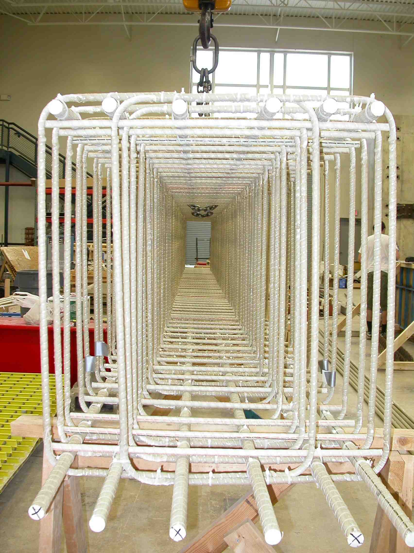
A example of an FRP-reinforced beam showing reinforcement details, with flexural rebar and properly spaced, vertically oriented stirrups. Source: Fabio Matta, Univ. of Miami
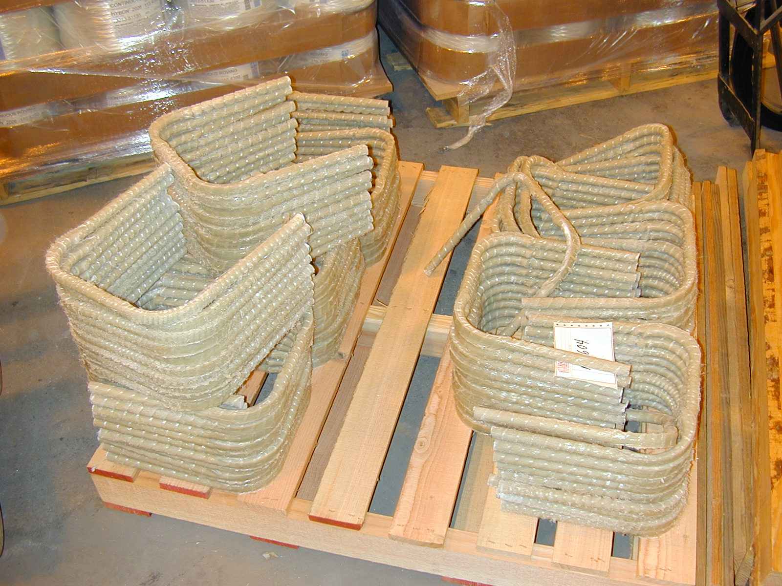
Examples of FRP stirrups for shear reinforcement, formed by bending FRP bar during manufacture. Source: Hughes Bros.
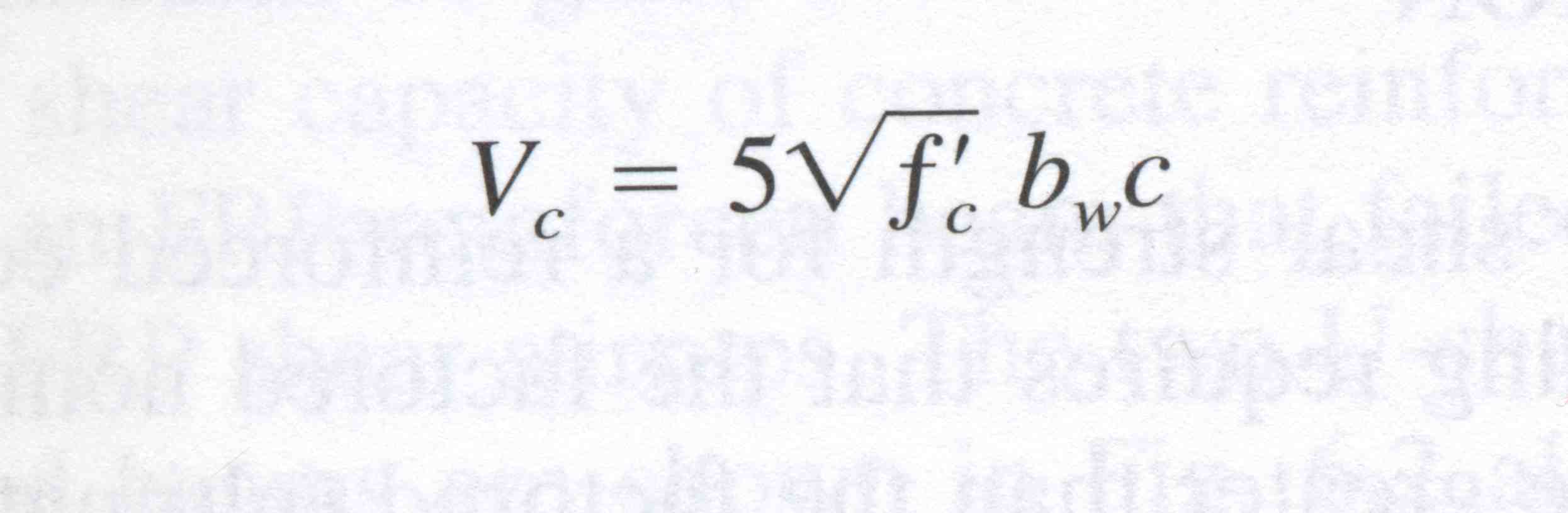
Fig. 1: ACI 440.1R-06 (equation 9-1).
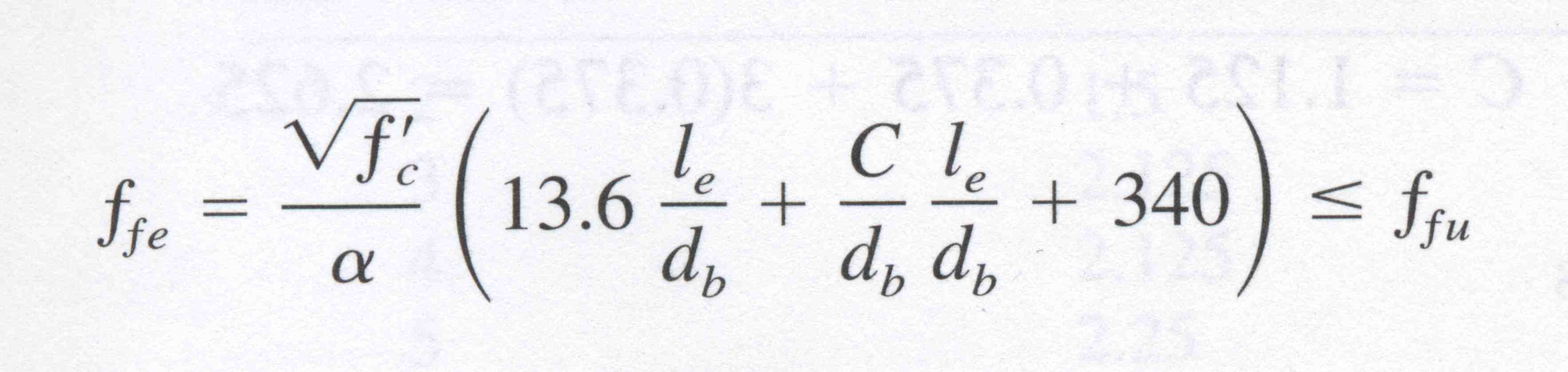
Fig. 2: ACI 440.1R-06 (equation 11-3).
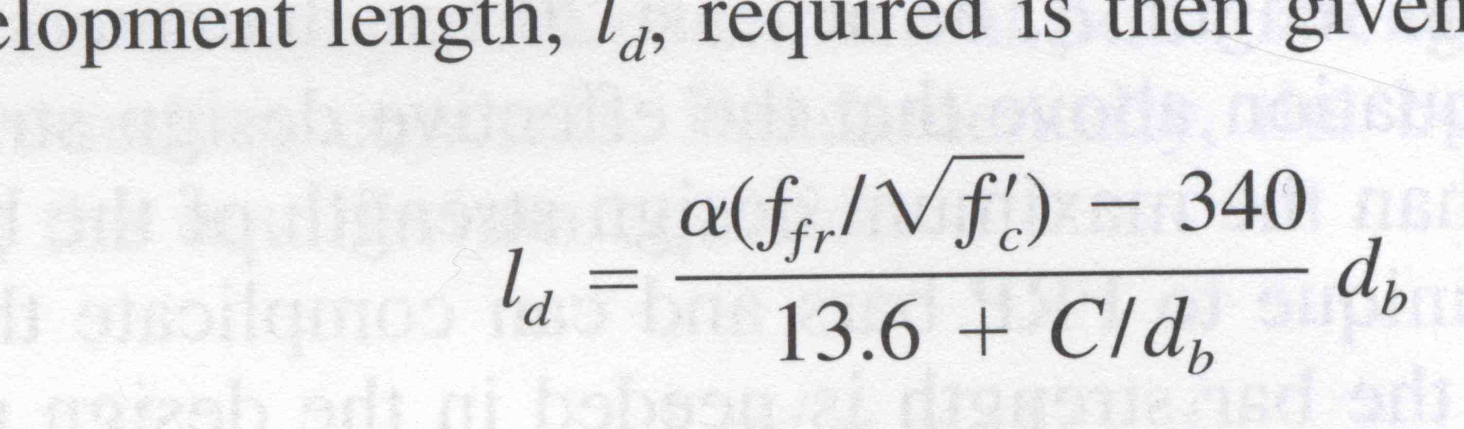
Fig. 3: ACI 440.1-06 (equation 11-6).
Share
Read Next


This second column taken from my new book Composites for Construction — Structural Design with FRP Materials (published by John Wiley & Sons Inc., New York, N.Y.) focuses on the design of concrete members that have FRP main tension reinforcing bars and are subjected to transverse shear forces (Chapter 6) and FRP reinforcement detail design (Chapter 7).
The flexural concrete members that fall into the scope of this column are slabs and beams. The design procedures presented here follow those of the American Concrete Institute (ACI) 440.1R-06, which is compatible with ACI 318-05 and follows the Load and Resistance Factor Design (LFRD) basis for strength with a resistance factor of ϕ = 0.75, the same factor that is used for steel-reinforced concrete as per ACI 318-05.
In a reinforced concrete section that develops a critical diagonal shear crack — one that initiates from a flexural crack at the bottom of the beam and propagates toward the top — the shear resistance comes from several sources: 1) the shear strength of the top portion of the beam, 2) frictional resistance between the two sides of the crack, known as aggregate interlock, 3) the vertical component of shear force carried in the main tensile reinforcement, or dowel action, which tends to prevent vertical crack growth, 4) the vertical force component provided by any additional reinforcing bars along the length of the beam, or shear reinforcement, and 5) any additional thrust provided by the compression arch, known as arching action, which develops in the beam roughly parallel to the shear cracks. Unfortunately, no analytical methods exist to quantitatively determine these factors — current practice is to lump everything, except for the shear reinforcement contribution, in a general category of shear capacity, or Vc. Typically, the value of Vc has been obtained empirically by testing beams that have steel main reinforcement but do not have shear reinforcement.
When an FRP-reinforced section and a steel-reinforced section are designed for the same moment-carrying capacity, the shear capacity of the FRP-reinforced section is much lower than the latter for a variety of reasons, but research and testing have confirmed that the main reason is the lower longitudinal modulus of the glass FRP bars.
The nominal shear capacity, Vn, of an FRP-reinforced beam, according to ACI 440.1R-06, is given as
Vn = Vc + Vf
where Vc is the concrete’s contribution to shear resistance and Vf is the contribution from FRP shear reinforcement, typically in the form of stirrups (the “f” subscript denotes the use of FRP rather than steel). The stirrups are typically bent into a “U” or rectangular shape and installed perpendicular to the longitudinal reinforcing bars.
The method for calculating Vc has evolved over time; the current equation in ACI 440.1R-06 (equation 9-1) is reproduced in Fig. 1, where bw is the width of the beam web and c is the depth of the neutral axis in the cracked elastic section as defined for the serviceability limit state flexural behavior; serviceability limit state flexural behavior is defined in Chapter 5 of my book. Note that the equation above is the traditional equation for the concrete shear contribution, Vc, multiplied by 2.5k (k being the ratio of the depth of the neutral axis to the effective depth of the section under service loads). Because FRP bars have less axial stiffness than steel, both the value of k and the contribution to the shear capacity will be less than in the case of steel.
The shear capacity of FRP stirrups, Vf, is calculated using equations similar to those given for steel stirrups. Note that the design strength of an FRP stirrup can’t be used in place of the yield stress of a steel stirrup, because FRP doesn’t yield like steel. The stress in an FRP stirrup is limited by its tensile strain or by its strength at its bent portion — for best performance, a minimum inside radius-to-diameter ratio of 3 is required for bent FRP stirrups, as per ACI 440.1R-06. This is because of stresses induced in the FRP bars when they’re bent, which can lead to premature linear-elastic failures.
As noted in my previous column (CT February 2007, p. 11), FRP bars can’t be bent in the field, unlike steel, and have to be produced with a bend by the manufacturer — typically only 90° bends are available. This requires close coordination with the manufacturer during the design phase to pre-order stirrups to specific dimensions.
The design process for FRP shear reinforcement involves determining the shear demand, Vu, which is calculated in the same way as in ACI 318-05, using the same loading as that used for the flexural design. The concrete's shear capacity, Vc, is calculated using the ACI 440.1R-06 equation 9-1, shown above. If Vu ≥ 0.5ϕVc , minimum FRP shear reinforcement must be provided, and if Vu ≥ ϕVc additional FRP shear reinforcement, Afv, must be provided. Use a resistance factor of ϕ = 0.75 to determine the factored shear strength of the member; if the shear demand is not met, revisit the overall beam design — greater beam thickness and/or more flexural reinforcement may be needed. Again, this is significantly different from a steel-reinforced design, where shear usually does not control member thickness.
The devil is in the details
The strength and serviceability calculations described above and in my previous article are used to determine the cross-sectional areas and bar sizes of the tension- (main) and shear-reinforcing bars in a beam or slab. These calculations do not, however, give the designer the length, spacing or location of the bars within the section, nor do they determine whether or not the bars are sufficiently anchored and embedded in the concrete throughout to ensure that calculated strengths will be obtained. This falls to "detailing," which is very important to the overall design and not a trivial construction-related item, as the term might imply.
To obtain bar spacing, the side distance for an FRP corner bar is calculated the same way as for steel. However, that minimum inside radius-to-diameter ratio of 3 or more, mentioned above, must be enforced. Figure 1shows the geometry of the corner bar and the parameters, A, B and C (clear cover, stirrup diameter and inside stirrup radius), which are used to calculate this distance. For example, assuming a beam with a No. 3 stirrup with an inside bend radius of 2.125 inches/60 mm and a side clear cover of 1.5 inches/38.1 mm gives a distance to the center of the corner bar of
A + B + C = 1.5 + 0.375 + 2.125 = 4.0 inches
A fundamental assumption of concrete design is that a “perfect” bond exists between rebar and concrete and that all tensile forces are transferred. ACI 440.1R-06 (equation 11-3) recommends that the maximum (effective) stress achievable in an FRP bar, which is controlled by bond failure, be taken as shown in Fig. 2, where C is the lesser of 1) the distance from the center of the bar to the nearest outer beam surface in the tension zone, or 2) half of the on-center spacing of the bars (side by side) and α is the bar location factor. C is 1.0 for bars that are in the bottom 12 inches/305 mm of the formwork when the concrete is cast, and is 1.5 when the bars are more than 12 inches above the bottom of the formwork (top bars). ACI 440.1R-06 further states that the term C/db (db being the bar diameter) not be taken larger than 3.5 and the minimum embedment length le be at least 20 bar diameters, or 20db.
The above equation indicates that the effective design strength of FRP rebar can be less than the maximum bar design strength based on tensile failure, primarily because FRP rebar has a very high strength relative to its modulus, compared to steel. This is unique to FRP bars and can complicate the design of flexural members because the details of placement are not precisely known at the time of initial design. To address this issue, sections that are bond-critical to the design of the beam and its capacity are obtained using the equations for an under-reinforced beam, and a resistance factor of ϕ = 0.55 is recommended. Alternatively, the beam can be redesigned as an over-reinforced beam using the lower bond-critical bar strength, and the resistance factor for an over-reinforced beam can be used: 0.55 ≤ ϕ ≤ 0.65.
The required bar length is that needed to anchor the bar in the concrete firmly enough to develop the tensile stress necessary for internal moment equilibrium at any section. Because the FRP bar may not be stressed to its full longitudinal design strength, ffu, at the maximum moment, the development length ld is given in ACI 440.1-06 (equation 11-6) as shown in Fig. 3.
All other ACI 318-05 provisions related to bars at inflection points and at bar cutoffs that are required for steel are also required for FRP. For simply supported beams, at least one-third of the main tension bars much extend over the support.
Excerpt published with permission. Copyright © 2007 John Wiley & Sons and Composites Technology. Composites for Construction — Structural Design with FRP Materials is available for $135 (USD) at www.wiley.com, or from www.bn.com, www.amazon.com or www.borders.com.


.jpg;maxWidth=300;quality=90;format=webp)
Related Content

Gatorbar, NEG, ExxonMobil join forces for composite rebar
ExxonMobil’s Materia Proxima polyolefin thermoset resin systems and glass fiber from NEG-US is used to produce GatorBar, an industry-leading, glass fiber-reinforced composite rebar (GFRP).
Read More
Swedish parking garage to incorporate decommissioned wind blades
Architect Jonas Lloyd is working with Vattenfall to design the multistory building with a wind blade façade, targeting eco-friendly buildings and creative ways to remove blades from landfills.
Read More
Sustainable Infrastructure Systems creates fiber-reinforced post-consumer plastic structural panels
Australian composites manufacturer offers a scalable building solution, already established in a pedestrian bridge application, to tackle unprocessed soft plastics waste.
Read More
Composites enable massive wastewater infrastructure project
To build complex drop shafts for New Zealand’s Central Interceptor project, RPC Technologies pushed the limits with glass and carbon fiber, vertical filament winding and UV-cure resins.
Read MoreRead Next

All-recycled, needle-punched nonwoven CFRP slashes carbon footprint of Formula 2 seat
Dallara and Tenowo collaborate to produce a race-ready Formula 2 seat using recycled carbon fiber, reducing CO2 emissions by 97.5% compared to virgin materials.
Read More
VIDEO: High-volume processing for fiberglass components
Cannon Ergos, a company specializing in high-ton presses and equipment for composites fabrication and plastics processing, displayed automotive and industrial components at CAMX 2024.
Read More
Plant tour: Daher Shap’in TechCenter and composites production plant, Saint-Aignan-de-Grandlieu, France
Co-located R&D and production advance OOA thermosets, thermoplastics, welding, recycling and digital technologies for faster processing and certification of lighter, more sustainable composites.
Read More