
Airline maintenance facility cuts repair costs while improving part quality
Delta TechOps uses simulation software to standardize repair procedures and bring work back in-house.


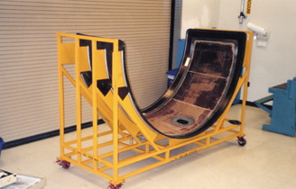
Source: Delta TechOpsBoeing 757 inlet cowl upper skin with the inner facesheet removed for repair. The tool holds the part shape during layup and serves as the cure fixture.
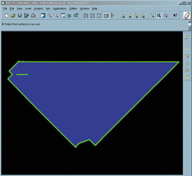
Source: Delta TechOpsFiberSIM generates a two-dimensional flat cutting pattern from the three-dimensional CAD model of the part.
Engineering design tools have proven their worth in product development. Accurate geometric modeling and structural simulations reduce development times, improve product quality and minimize or eliminate expensive trial-and-error prototyping. Engineers are now beginning to learn that these tools can bring the same benefits to the entire product life cycle. In particular, repair processes can be optimized by applying the same types of analyses used in the original part design.
Delta Technical Operations (TechOps) provides maintenance for Delta's (Atlanta, Ga., U.S.A.) entire fleet of commercial airliners and offers services to other airlines, as well. The main TechOps Center is located at Hartsfield-Jackson International Airport (Atlanta, Ga., U.S.A.). About 5,000 ft² of the 2.7 million ft. facility is set aside for repair of composite engine components. This bonding shop is supported by 107 licensed mechanics and six engineers, four full-time and two contract.


Engine cowls susceptible to damage
One of the largest composite components repaired by Delta TechOps is the inlet cowl upper skin for the Boeing 757. The inlet cowl is part of the aerodynamic structure called the engine nacelle, which encases the jet engine. (See HPC's nacelles feature in this issue, p. 49. The upper skin is about 1.2m/4 ft wide, has a 2.1m/7 ft diameter, and covers roughly 180°. The cowl skin is a sandwich structure with a 15.24-mm/0.60-inch thick, 4 lb/ft3 Nomex core produced by Hexcel Corp. (Stamford, Conn., U.S.A.). The outer facesheet comprises one ply of 120 aramid/epoxy prepreg oriented at ±45° and one ply of eight-harness satin carbon/epoxy prepreg oriented at 0°/90°; the inner facesheet comprises the same two plies plus an additional 10 smaller doubler plies consisting of 3K carbon/epoxy prepregs oriented at ±45° and 0°/90°. All materials are procured to Boeing specifications from qualified suppliers like Hexcel and Cytec Engineered Materials (Tempe, Ariz., U.S.A.).
The inlet cowl upper skin requires frequent maintenance. "We see two to three of them every month," says Brian McNichols, a senior engineer at TechOps. "Most of the damage is delamination, caused by water ingression, around a maintenance access port that is built into the skin." The aramid ply is located against the core and tends to absorb water more than carbon materials. The aircraft is exposed to large temperature variations during normal operations, causing the water to repeatedly freeze and thaw, leading to core delaminations and other types of damage. Damage also results from aerodynamic erosion and wear from field maintenance.
Aircraft mechanics inspect the cowls when they arrive at TechOps. Visual indications of damage include surface defects such as pinholes, erosion and small cracks. Coin tap tests provide a quick and inexpensive method to check for delaminations. Suspicious areas identified by these tests are inspected in more detail using through transmission ultrasonic (TTU) methods. Technicians use handheld and wheel transducers from Sonatest Inc. (San Antonio, Texas, U.S.A.) or air coupled equipment from NDT Systems Inc. (Huntington Beach, Calif., U.S.A.).
According to McNichols, the initial damage size is often small, about 305 mm (12 inches) in diameter. In most cases, though, the entire inner facesheet is replaced. "The damage on each part is unique, so repairing just the damaged area would require a specific engineering design. Also, the presence of moisture in the honeycomb cells adjacent to the repair often result in additional delamination, when repairs are cured at elevated temperatures," explains McNichols. "If we replace the entire skin, we can use the same design for all of the cowls." Removal of the facesheet also allows the core to be dried out, improving the quality and success rate of the repair.
Before the facesheet is removed, technicians place the cowl skin in a bond tool. This tool holds the shape of the part after the facesheet is removed, and also serves as the cure tool when the part is placed in the autoclave. The inner facesheet is removed by peeling and grinding the plies. If additional core damage is found, the core may be replaced. Although this process is labor intensive, it is still less expensive than replacing the entire part.
It is in the next step, designing and cutting the replacement plies, that the engineering tools prove their worth. "Designing the flat patterns was our toughest challenge," says McNichols. "The cowl has a complex, curved surface." In the past, technicians would place a sheet of vacuum bagging film on the part, remove the wrinkles, and then trace the outline of the part. This shape would then be used to generate flat patterns for the prepreg cloth. Splices were added, based on past experience, in order to minimize potential fabric distortion. Because of the uncertainty in the process, extra material was left on the borders, but much of this would be trimmed off during layup.
The process was so complex that cowl skin repairs were often delayed for many months. TechOps usually outsourced the repairs, accepting an increase in costs in exchange for more timely repairs. Delta engineers realized, however, that they could save both time and money by standardizing the repair process and bringing the work back in-house.
Software simulates repairs
The Delta team turned to FiberSIM from VISTAGY Inc. (Waltham, Mass. U.S.A.) to design the ply patterns. FiberSIM is a specialized program that works in conjunction with CAD programs to generate flat patterns from three-dimensional surfaces and to perform draping analyses (see HPC May 2002, p. 52).
To work with FiberSIM, the Delta engineers first had to get the cowl surface geometry into a CAD program. Using two-dimensional drawings from Boeing, they were able to create 3-D geometry within ICEM Surf, a CAD surfacing program from ICEM Ltd. (Southampton, U.K.). These surfaces were then imported into FiberSIM. The layup schedule, which is the same as the original facesheet with the addition of one repair ply, was input into the program. The engineers next performed a draping analysis with FiberSIM, identifying areas where fiber distortions were too large. Repair specifications required that fiber angles be within roughly ±5° for fabric plies and ±3° for unidirectional plies. "With FiberSIM, we could show that we met the drawing requirements for the orientation of the fabric warp," says McNichols. "With the manual method, it was almost impossible to determine what tolerances were met."
With the draping analysis complete, the engineers then used FiberSIM to generate flat patterns. These were plotted onto Mylar film and cut out to create permanent templates for tracing and cutting the composite plies. In addition to improving the fiber orientation, the company maintains that FiberSIM simulation also improved the overall pattern shape. "We reduced our scrap rate on the wasted border trim by about half," says McNichols.
After the plies are cut, the repair proceeds like any other layup. First a layer of film adhesive is applied over the core and solid laminate edgeband and then the repair plies are laid up onto the part, after which a final layer of film adhesive is applied as a surfacing film. The part is then cured in an autoclave at 3.1 bar (45 psi) at a temperature of 177°C/350°F for two hours.
More room for improvement
The new standardized process has allowed TechOps to bring the inlet cowl upper skin repairs back in-house, for an annual cost savings of about $500,000 (USD). Repair time has been cut to roughly two weeks, down from the original three or four weeks. Even more cost savings can be achieved by further automating the process. By standardizing on full skin repairs, TechOps has reduced the need to generate unique patterns for each repair. This has allowed them to procure pre-cut kits from HEATCON Composite Systems (Seattle, Wash., U.S.A.), and they are exploring similar services with CAD Cut Inc. (Marblehead, Mass., U.S.A.).
The approach has been so successful that TechOps is using it to lower costs in other areas. "Now we're applying the same approach to our other large composite parts, such as the lower inlet cowl and the fan cowl skins," explains McNichols. "FiberSIM has been easy to learn and to use. Getting the surface data into the CAD system is more difficult than creating the ply patterns." Bringing the repairs back in-house has not only cut costs, it has improved part quality.


Related Content

Infinite Composites: Type V tanks for space, hydrogen, automotive and more
After a decade of proving its linerless, weight-saving composite tanks with NASA and more than 30 aerospace companies, this CryoSphere pioneer is scaling for growth in commercial space and sustainable transportation on Earth.
Read More
Combining multifunctional thermoplastic composites, additive manufacturing for next-gen airframe structures
The DOMMINIO project combines AFP with 3D printed gyroid cores, embedded SHM sensors and smart materials for induction-driven disassembly of parts at end of life.
Read MoreComposites manufacturing for general aviation aircraft
General aviation, certified and experimental, has increasingly embraced composites over the decades, a path further driven by leveraged innovation in materials and processes and the evolving AAM market.
Read More
Plant tour: Middle River Aerostructure Systems, Baltimore, Md., U.S.
The historic Martin Aircraft factory is advancing digitized automation for more sustainable production of composite aerostructures.
Read MoreRead Next

Developing bonded composite repair for ships, offshore units
Bureau Veritas and industry partners issue guidelines and pave the way for certification via StrengthBond Offshore project.
Read More
“Structured air” TPS safeguards composite structures
Powered by an 85% air/15% pure polyimide aerogel, Blueshift’s novel material system protects structures during transient thermal events from -200°C to beyond 2400°C for rockets, battery boxes and more.
Read More
All-recycled, needle-punched nonwoven CFRP slashes carbon footprint of Formula 2 seat
Dallara and Tenowo collaborate to produce a race-ready Formula 2 seat using recycled carbon fiber, reducing CO2 emissions by 97.5% compared to virgin materials.
Read More