Breathing-mold process yields sandwich composite from LFT
In-cavity foaming and controlled mold-opening technique creates core and faceskins from a single injection molded material, reducing part mass and boosting performance.
A joint research project by the Fraunhofer Institute for Chemical Technology (F-ICT, Pfintzal, Germany) and the Fraunhofer Project Centre for Composites Research (FPC, London, ON, Canada) has been looking at methods to reduce mass but improve mechanical performance of injection molded parts made from pelletized long-fiber thermoplastic (LFT). Research has led them to accomplish these goals by injection molding a functional sandwich composite, employing an in-mold foaming technology and the breathing-mold (controlled mold-opening) technique. The result is a foamed core between solid faceskins — both reinforced with chopped glass — from a single, pelletized LFT material, formed in a single shot.
Making foam and faceskins in mold
Researchers create the foam by using either a chemical blowing agent (CBA) or physical insertion of an inert-gas blowing agent (PBA). In either case, the blowing agent is introduced to the melt during plastification in the barrel, prior to injection. The rotating screw mechanically mixes the dissolving blowing agent or inert gas (typically N2 or CO2) with the polymer melt, creating a single-phase gas/polymer mixture in front of the screw. Control of back pressure, screw position and shutoff valves/nozzles is carefully managed to ensure that the gas stays in solution before injection into the cold mold, which must be well vented. As the melt flows into the tool, it experiences a pressure drop, which enables the trapped gases to begin expanding. This foams the core.
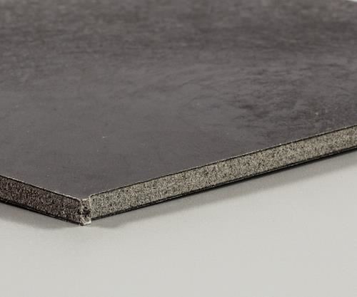
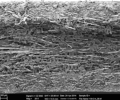
At this point, the breathing-mold technique comes into play. The tool is held slightly open during initial fill, is shut during the packing stage, then reopened (again, slightly) and held open through part ejection: After injection and a short delay (5-10 seconds) during which skin layers freeze off, foaming is accelerated by controlled mold opening while polymer in the core is still molten. Packing helps consolidate and solidify the skin layers and form the faceskins (see photo below). Opening the tool a precise distance — the gap varies by material and part design but a typical range seen in testing was between 2.5 and 3.6 mm — for the balance of the molding cycle causes a further pressure drop, speeding movement of gas out of the molten polymer. As the melt solidifies, foaming slows to a stop (residual gas is vented off ) and then the part is ejected. (Not new, this technique is also called core back, negative embossing, foaming with decompression, or precision mold opening and sometimes is used in conventional injection molding to improve surface finish because higher cavity pressures can be achieved.)
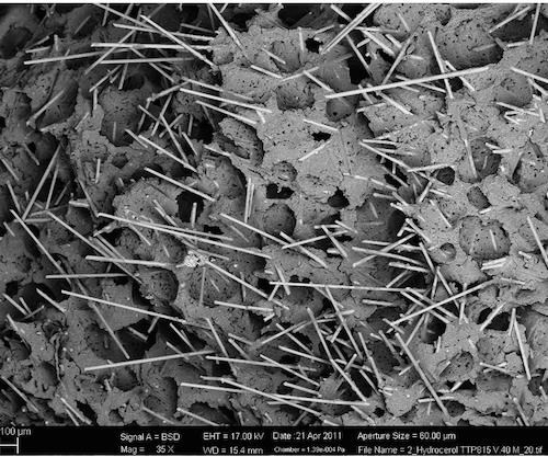
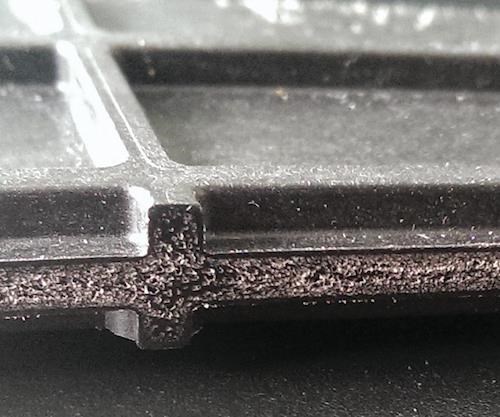
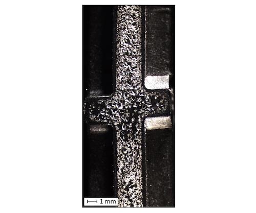
Foams form in the neutral axis where the cellular structure maintains a constant distance between the solid, load-bearing faceskins, which, in turn, form an I-beam or sandwich-like structure. This combination reduces mass/unit area, augments acoustical damping, boosts impact strength, improves dimensional stability (reducing warpage) and increases specific bending stiffness vs. a solid structure of the same design and resin/reinforcement (thanks to a higher moment of inertia). Further process benefits include reduced clamping force, shorter cycle times and lower melt viscosity, yielding a lighter, more structurally sound part at lower energy cost than an injection molded solid resin with reinforcement of the same type, helping to offset higher tooling costs. Significantly, the resulting structure forms consistently across the entire length and width of a part, regardless of its complexity or internal geometry (e.g., ribs; see photos below).
Blowing agent and pressure options
Those who use the process must select from two foaming options, each of which has inherent advantages and disadvantages. Chemical (CBA) foaming advantages include its availability from many suppliers and that it is added as a masterbatch (where it dissolves, forming a gas during heating and plastification). Disadvantages are that CBAs have temperature limitations and may leave a chemical residue on parts, which can cause discoloration or an odor. Advantages of inert gas (PBA) foaming are that there are no temperature restrictions, it leaves no chemical residue on parts, higher foaming pressures can be achieved, better control of the amount of gas used is possible and more gas can be added to the melt if needed. Disadvantages? Additional equipment and licenses are required.
Processors also must select from two options in regard to filling the tool. In the “low-pressure” option, the tool cavity is only partially filled during injection. Material shrinkage against the tool (that otherwise could lead to short shots) is countered by expanding gas (and polymer) as blowing pressure alone is used to complete the fill. This technique eliminates the need to apply packing pressure after injection. The packing step is bypassed and, therefore, the tool remains slightly open. It also reduces clamping pressures (enabling a standard press to mold larger parts than normal or a smaller, less costly press to mold the same-size part) and yields lower residual stresses inside parts, which then are less prone to warpage. Disadvantages are that it results in a part with higher density (reportedly 5-15% higher, depending on ratio of wall thickness to flow length) and more streaking on part surfaces, which can be an issue in aesthetically sensitive applications.
With the alternative high-pressure process, the mold cavity is filled the conventional way (solely with injection pressure) and then packing pressures are applied only for a few seconds. Advantages here are a more homogeneous foam, a part with lower density (reportedly, more than 50% lower density can be achieved) and better part surfaces, because skins freeze sooner and high pressures smooth out rough surfaces after injection. This technique, however, requires a tool with a shear edge and a press with a short-stroke tool frame or multi-core back (which adds to cost), so the tool can be precisely opened part way through the molding cycle.
Interesting benefits
Several benefits occur as a result of combining precision mold opening with integral reinforced foaming. First, as wall thickness increases, the second moment of inertia increases three-fold, making this low surface-mass (low mass/unit area) technology potentially attractive for large, semi-structural parts subject to bending loads, such as door interior-trim panels, spare-wheel wells, seat shells and backrests, underbody shields and instrument panel supports in the automotive industry. Second, because skins solidify before the tool reopens, gas bubbles don’t break through and pressures further smooth the surface, leaving a good finish on both sides of the part. In fact, the longer the delay between initial injection and mold opening, the thicker the solid skins become relative to the foamed core (and vice versa), making this a process parameter that can be controlled to meet application needs.
Quantifying process choices on final properties
To better understand the effects of various foaming and filling options on final part properties, a research team led by Alexander Roch, head of Thermoplastic Technology Corridor, F-ICT, compared results for two materials during two trials held several years apart:
• 30% LGF polypropylene — PP-LGF30; initial pellet length 11 mm; from Dow Automotive Systems (Midland, MI, US).
• 50% LGF polyamide 6 — PA6-LGF50; initial pellet length 12 mm; from BASF (Ludwigshafen, Germany).
Foaming was achieved either with CBA (endothermic commercial grades from Clariant Masterbatches GmbH, Muttenz, Switzerland) or PBA (N2 in the MuCell microcellular foam process from Trexel Inc., Wilmington, MA, US). All samples were molded on the same injection molding press (Engel duo 700 pico combi M, ENGEL AUSTRIA GmbH, Schwertberg, Austria) equipped with both standard and MuCell injection units. For CBA foaming, a 105-mm-diameter screw was used. For PBA foaming, a second MuCell injection unit and an 80-mm-diameter screw were used. (Existing screws that worked for each process and whose flights were optimized for long-fiber materials were used.)
Researchers molded flat sheets (500 mm by 500 mm) in each combination of resin and blowing agent. Only the high-pressure fill technique was employed, using a shear-edge tool equipped with an edge-mounted, 5-mm-wide needle shut-off nozzle/valve as the gate. Owing to density differences between the two materials, the initial mold gap (PP-LGF30, 3.6 mm; PA6-LGF50, 2.5 mm) was adjusted so the injected volume of material for each shot was a constant, allowing researchers to achieve consistent surface weight (mass/unit area) for both materials. Use of the breathing- mold technique enabled researchers to control plaque nominal wall thickness, density and final volume. All other molding conditions were kept constant for each material system. Unfoamed reference plaques were molded as controls.
Overall, results showed that for constant surface weight, bending stiffness increased by up to 600% and a small increase in wall thickness led to a significant increase in flexural rigidity, regardless of which blowing agent was used. At the greatest density reduction, bending stiffness for PP-LGF30 increased ≈330% with CBA and ≈275% with PBA foaming, while for the PA6-LGF50 (where density reductions between foaming agents were significantly different), bending stiffness increased ≈190% with CBA and ≈630% with PBA.
As would be expected, thicker skins (achieved via longer delays before mold opening) yielded increased bending stiffness and impact strength, but tensile properties decreased slightly (possibly because there was less material in the core to resist pulling forces).
Falling Dart impact tests showed that unlike conventional unreinforced foams, which tend to become more brittle after foaming, energy absorption in foamed PA6-LFG50 improved vs. unfoamed controls. Charpy bending tests done on PP-LGF30 showed nearly constant behavior with increasing density reduction. Notably, with PA6-LGF50 samples, there was little difference in the degree of impact strength increase, regardless of which foaming agent was used. Among PP-LGF30 samples, those foamed with CBA showed much greater impact strength than those foamed with PBA, but couldn’t meet 50% density-reduction targets.
At higher mold-opening strokes, CBA parts had large sink marks. This might be because N2 gas used in PBA had higher blowing pressures than CO2 devolved from CBA, and that led to measurably thicker cores and thinner skins for PBA-foamed samples, and the reverse for CBA-foamed samples. (Each gas showed different dissolving, diffusion and foaming behavior. More recent testing using CO2 for the PBA gas shows it delivers lower pressure but not automatically thicker skins.) Also, researchers theorize that the combination of smaller screw diameter, an additional non-return valve, plus the gas-mixing zone of the MuCell unit caused greater fiber breakage in PBA samples than occurred in CBA samples. Another difference that could have affected results is that PA6 materials were processed at higher melt temperature, which might have enabled blowing agent to leak from the feed zone of the injection barrel. Yet another possibility is that the higher viscosity of PA6 might have hindered bubble formation during foaming.
“By combining chemical or physical blowing agents and the breathing-mold technique, reinforced sandwich composites with significant mass-reduction potential can be produced in a single step and at rates appropriate for high-volume manufacturing,” notes Roch. “Given this, we think the technology will be interesting to automotive molders using LFT materials.”
Work on the technology has continued, and at this year’s SPE ACCE in Detroit (Sept.7-9, 2016), Roch will present a paper on use of the technology to produce an air-guide panel for a next-generation BMW 7 Series car (BMW AG, Munich, Germany). The co-molded part uses a hard PP and a soft thermoplastic elastomer (TPE) plus the breathing-mold technique to reduce material usage 20% vs. a solid co-molded part.
Related Content
Plant tour: Joby Aviation, Marina, Calif., U.S.
As the advanced air mobility market begins to take shape, market leader Joby Aviation works to industrialize composites manufacturing for its first-generation, composites-intensive, all-electric air taxi.
Read MoreInfinite Composites: Type V tanks for space, hydrogen, automotive and more
After a decade of proving its linerless, weight-saving composite tanks with NASA and more than 30 aerospace companies, this CryoSphere pioneer is scaling for growth in commercial space and sustainable transportation on Earth.
Read MoreThe lessons behind OceanGate
Carbon fiber composites faced much criticism in the wake of the OceanGate submersible accident. CW’s publisher Jeff Sloan explains that it’s not that simple.
Read MoreThe potential for thermoplastic composite nacelles
Collins Aerospace draws on global team, decades of experience to demonstrate large, curved AFP and welded structures for the next generation of aircraft.
Read MoreRead Next
All-recycled, needle-punched nonwoven CFRP slashes carbon footprint of Formula 2 seat
Dallara and Tenowo collaborate to produce a race-ready Formula 2 seat using recycled carbon fiber, reducing CO2 emissions by 97.5% compared to virgin materials.
Read More“Structured air” TPS safeguards composite structures
Powered by an 85% air/15% pure polyimide aerogel, Blueshift’s novel material system protects structures during transient thermal events from -200°C to beyond 2400°C for rockets, battery boxes and more.
Read MorePlant tour: Daher Shap’in TechCenter and composites production plant, Saint-Aignan-de-Grandlieu, France
Co-located R&D and production advance OOA thermosets, thermoplastics, welding, recycling and digital technologies for faster processing and certification of lighter, more sustainable composites.
Read More
.jpg;width=70;height=70;mode=crop)


.jpg;maxWidth=300;quality=90)


