Carbon fiber/epoxy wheels developed to replace metal wheels on large freight trailers
Semi-trailers roll lighter with Prins Dokkum's carbon fiber Dynawheels.
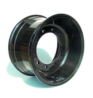
The trucking of freight across continents is an enormous and growing industry, as anyone who drives the roads of Europe and North America can attest. Limited by gross weight restrictions (vehicle plus payload), the transport industry has looked to composites to reduce vehicle weight, thereby improving fuel economy and permitting more paying cargo to be carried on each trip. Composite materials proved their durability in semi-tractor exterior body panels in the 1980s. In recent years, composites have moved into semi-structural components - most notably, the commercially successful replacement of aluminum and steel in the trailer structure and cargo box achieved by Composittrailer N.V. (Lokeren, Belgium) and U.S. licensee Martin Marietta Materials (Raleigh, N.C., U.S.A.) and reported in CT February 2003, p. 36. In Europe, Prins Dokkum B.V. (Dokkum, The Netherlands) has pushed the lightweight envelope even closer to the road - creating the first commercial heavy-duty trailer wheel constructed solely of composite materials. Subject to extreme impact and fatigue loads, the carbon fiber/epoxy wheels, sold under the trade name Dynawheel, have won approval during extensive independent laboratory and field trials and, today, are used on trailers throughout Western Europe.
Prins Dokkum has more than 60 years of experience in the production of steel wheels for automobiles, trailers and other vehicles, and produces steel components for greenhouses and "road furniture" (guardrails, crash barriers, etc.) as well. In 1994, however, the company made a strategic decision to acquire the technology necessary to design, develop and produce low-weight structural composite parts. Jan van der Meulen, project manager, composite products for Prins Dokkum explains that, given the company's core business and its understanding of the performance requirements, Prins Dokkum targeted highly loaded freight trailer wheels for conversion to composites. Van der Meulen describes the objective of the wheel development as "less fuel, more load," targeting its use on bulk trailers where a reduction in vehicle weight translates immediately to greater payload and revenue for the transporter.
The Dynawheel posed sizable design challenges. The composite wheel would have to handle not only radial loads but diverse loads imposed during cornering, impact and braking, as well. Additionally, it would need to meet multiple functional requirements, including airtightness and exact fit to the hub, tire and brake drum. The major concern, notes van der Meulen, was to avoid high out-of-plane and high interlaminar shear stresses, which place loads on the resin matrix rather than the fiber and can result in delamination of anisotropic, two-dimensional composite materials, such as woven fabrics - especially under the significant fatigue loads experienced by the wheel.
In the early development, finite element analysis (FEA) was used to compare design characteristics such as fiber orientation and wall thickness. Initial modeling was conducted, using EMRC-NISA software (Engineering Mechanics Research Corp., Troy, Mich., U.S.A.), and later refined with MSC/NASTRAN (MSC.Software Corp., Santa Ana, Calif., U.S.A.). Initial designs in hand, Prins Dokkum began fabrication of prototype wheels.
Extensive certification testing validates design
Before the prototypes could be put into production and offered for sale, the Dynawheel had to attain certification from the German TÜV validation laboratories. This certification consisted of a number of durability tests on wheel/tire assemblies, each of which was passed, emphasizes van der Meulen, resulting in TÜV approval in September 2001. First up was a simulated cornering fatigue test, in which the wheel is subjected to a rotating bending moment of 30 KNm/22,100 ft-lb for 2 million revolutions, and 20 KNm/14,750 ft-lb for 10 million revolutions. Passing requires a less than 10 percent loss of wheel stiffness.
The radial load test simulated straightforward driving. The wheel must experience no loss of air pressure under an axial load of 90 KN/20,200 lbf (lb of force) per wheel for 17,000 Km/10,600 miles in a vertical position, and under an axial load of 67.5 KN/15,200 lbf for 13,000 Km/8,100 miles while canted at 17.5° from vertical. The impact test simulated hitting a curb. The wheel must maintain full air pressure after a 1,000 kg/2,200 lb weight is dropped from a 600-mm/23.6-inch height onto the edge of the rim.
These two severe conditions are combined in the impact/radial load test: the rim is impacted with the 1,000 kg/2,200 lb weight from 400 mm/15.7 inches, then the wheel is subjected to an axial load of 90 KN/20,200 lbf for 13,000 Km/8,100 miles. Again, no air loss is permitted.
A pressure test is completed, requiring no leaking at 25 bar/368 psi. Van der Meulen explains that, for safety reasons, this is performed using water in the tire instead of air, in the event the tire ruptures (as it has, on occasion). Finally, the wheels are subjected to severe and continuous braking to simulate mountain driving. A passing score requires the maximum temperatures of the hub, brake drum, wheel center and inner rim shoulder (the wheel area in contact with the tire) to be equal to or below those observed on steel or aluminum wheels.
Field trials began in 1995, with careful tracking of tire pressure, wheel nut tightening torque, tire life and brake life. Evaluation of early prototypes that exhibited minor air leakage pointed out that preform quality (no wrinkles) and injection parameters during production molding are critical to performance. Further refinements were made empirically, based on the results of laboratory and field tests of the wheels, and a small number of wheels continue to be tracked for long-term evaluation.
Preforming, VARTM achieve manufacturing consistency
Based on the extensive testing, the certified production version of the Dynawheel features a sophisticated three-dimensional, three-part carbon-fiber preform, with a combination of woven and noncrimp fabrics, augmented in several locations with carbon fiber tows and infused with a liquid epoxy resin by vacuum-assisted resin transfer molding (VARTM). In some areas of the wheel, woven cloth supplied by Sigmatex (Runcorn, U.K.) and Hexcel Composites (Duxford, U.K.) is used, while other sections are reinforced with noncrimp fabric supplied by SAERTEX (Saerbeck, Germany) and large-format carbon tows. The fabrics are based on 12K carbon tow while the large tow, supplied by SGL TECHNIC Ltd. (Leatherhead, U.K.) and Zoltek Corp. (St. Louis, Mo., U.S.A.), is used in both 60K and 400K formats. Average fiber volume is 55 percent.
Van der Meulen explains that woven fabric is better in interlaminar shear, but the noncrimp fabric has better in-plane properties, so each material is used where the specific need is greatest. The fibers in the hub of the wheel are oriented in the radial and tangential directions, while the reinforcement in the rim is oriented circumferentially and axially, making the three-piece hub/rim design a satisfying answer to initial concerns about out-of-plane and interlaminar stresses.
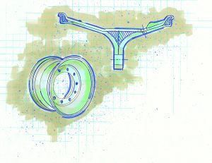
For each wheel, the fabric is cut into more than 100 individual ply sections by means of a CNC-cutting machine. These plies are placed in three preform machines and consolidated under pressure using a tackifier. Two of the resulting preforms are "cup" shaped. Placed "cup bottom to cup bottom," these form the wheel hub. The remaining preform forms the cylindrical wheel rim. The hub and rim preform are joined on a fixture. The center of the Dynawheel at the intersection of the hub and the rim is not highly stressed and therefore, to keep mass low, two core rings of polyurethane foam fill the space between the hub and rim (see the illustrated wheel cross-section, p. 44). Unidirectional tows are used as filler in the intersections (to eliminate resin-rich areas) and to create specific features, such as the edges of the rim. With the preforms still in the fixture, bolt holes and the valve hole are punched out in one stroke of a hydraulic press by means of a die fitted with hollow pipes with sharpened ends. Then the preform assembly is placed in a four-piece, heated aluminum mold, which can be opened and closed hydraulically. Injection occurs over a period of 10 minutes, using epoxy resin supplied by Bakelite AG (Iserlohn-Letmathe, Germany). It has an amine-based hardener and was selected for its relatively high heat distortion temperature, good mechanical (fatigue) properties and processability. The part is cured at 80°C/176°F, and 45 minutes after the start of injection the wheel is demolded. After molding, a batch of wheels is post cured in an oven at 140°C/284°F and coated with two coats of two-component acrylic/polyurethane. The wheels may be painted in any color or clearcoated to show off the "carbon fabric look."
All tooling was designed, developed and produced by Prins Dokkum. The company has developed special injection equipment to compensate for the resin shrinkage after the mold is filled without losing the ability to clean the injection system after each injection. The injection and overflow tubes are connected to the mold in a way in which they can be removed quickly and without any cleaning. The mold can be evacuated to 1.5 mbar/ 1.125 mm Hg absolute pressure using only a low-capacity vacuum pump. The finished surface quality is very dependent on the location of the injection and overflow/vacuum ports. Since a preform assembly will always have some loose fibers that can be pinched between two mold sections, the mold has room for these fibers at the parting lines to avoid damage. These flash areas will be filled with resin during the injection, and are easily removed after molding by means of air driven, diamond-coated tooling.
The maximum thickness in the hub section is 24 mm/0.95 inch, and in the rim a nominal 12 mm/0.47 inch, except at the rim edges where it thickens to contain the tire bead. Early versions of the wheel had high-strength aluminum inserts molded into the bolt holes, meant to contain the 600 Nm/443 ft-lb bolt tightening torque used to secure the wheel to the trailer hub. After extensive lab and road tests, these inserts proved unnecessary and were removed from the design. Prins Dokkum was pleased to discover the wheels could be directly bolted to the hub through the carbon fiber composite without excessive creep and corresponding loss of bolt torque.
Roadworthy and rolling
The Dynawheel is sized to fit 298-mm/11.75-inch wide tires with a nominal tire diameter of 572 mm/22.5 inches. Each wheel weighs 19.0 kg/41.8 lb, compared to approximately 25 kg/55 lb for aluminum and 45 kg/99 lb for steel wheels. In a three-axle configuration (six wheels, total), switching from steel to composite results in a trailer weight reduction of as much as 156 kg/343 lb. Once considered secondary selling points, the wheel's high-tech appearance and easy-to-clean surface have proved to be as important as its low weight - a trailer equipped with Dynawheels is a stand out, and trailer owners appreciate the fact that no weekly cleaning of the wheels is required to keep them shining.
With the Dynawheel selling well in Western Europe - initial demand highest in The Netherlands and Germany - Prins Dokkum is discussing licensing and distribution arrangements with potential North American representatives and also is active in the development of other lightweight composite components for several European automotive manufacturers, using similar technology.
Related Content
Composite resins price change report
CW’s running summary of resin price change announcements from major material suppliers that serve the composites manufacturing industry.
Read More3D weaving capabilities achieve complex shapes, reduce weight and cost
JEC World 2024: Bally Ribbon Mills is displaying film-infused 3D woven joints, woven thermal protection systems (TPS) and woven composite 3D structures.
Read MoreHighly tunable, woven lattice reinforcements target automotive structures
CAMX 2023: Startup Weav3D will be demonstrating its two collaborative automotive demonstrator parts and present two conference papers.
Read MoreBraskem demonstrates PP solutions using Weav3D composite lattice technology
Partnership combines Braskem’s polypropylene sheets with Weav3D Rebar for Plastics technology to address new structural, automotive applications requiring high-strength, lightweight material solutions.
Read MoreRead Next
VIDEO: High-volume processing for fiberglass components
Cannon Ergos, a company specializing in high-ton presses and equipment for composites fabrication and plastics processing, displayed automotive and industrial components at CAMX 2024.
Read MoreDeveloping bonded composite repair for ships, offshore units
Bureau Veritas and industry partners issue guidelines and pave the way for certification via StrengthBond Offshore project.
Read More“Structured air” TPS safeguards composite structures
Powered by an 85% air/15% pure polyimide aerogel, Blueshift’s novel material system protects structures during transient thermal events from -200°C to beyond 2400°C for rockets, battery boxes and more.
Read More


