Carbon/glass hybrids used in composite wind turbine rotor blade design
As turbine blades grow to greater lengths, composite blade manufacturers take a long look at carbon/glass hybrids.
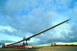
Sometime this year, the swept area of the world's largest wind turbine will grow by nearly 30 percent. Swept area describes the circular zone outlined by the tips of a turbine's turning rotor blades, indicating how much wind is being "harvested" - a key factor affecting a turbine's potential power output. The greater harvest will come courtesy of a new 61.5m/200 ft blade from LM Glasfiber (Lunderskøv, Denmark) - 24 ft longer than any blade now in service.
Building lightweight blades of greater length remains a primary focus for utility-size turbine manufacturers because investment in blade technology pays off: When installed on a 5 MW turbine owned by REpower Systems AG (Hamburg, Germany), LM's record-setting blades will increase rotor diameter to 125m/410 ft, with a swept area the size of two-and-a-half soccer fields, swelling maximum turbine power output from 4.5 MW to 5 MW. And because the blades account for only about 10 percent of the overall capital expense for a wind turbine, spending on blade innovations is a relatively small factor in energy production costs. Moreover, the benefits of better structural designs and improved fabricating techniques cascade throughout the turbine's cost structure. A lighter and/or more efficient blade decreases the demands on the hub components and tower structure, decreasing capital and operating expenses for the entire turbine. Those benefits, however, don't come easy. As blades have grown longer, manufacturers have pushed the limits of fiberglass-reinforced composite technology.
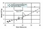
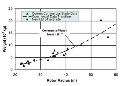
"The difficulties associated with large blades do not increase in simple proportion to their length," says Frank V. Nielsen, LM Glasfiber R&D director. While swept area increases by approximately the square of blade length (an exponent of 2), blade weight, by rule of thumb, should grow with the cube of length (an exponent of 3). In practice, weight increases have been mitigated by refining designs and employing manufacturing methods that optimize the composite's structural properties. Studies, therefore, have shown actual weight to increase by an exponent of 2.35. Nonetheless, Nielsen says, "The real challenge lies in developing a large blade that incorporates the best possible combination of capacity, weight and price."
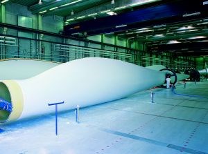
Such was the case, for example, on LM Glasfiber's 54m/176-ft long glass/epoxy 54P offshore model, currently, the largest installed blade. Rated at up to 4.5 MW, it was put into service in late 2003 on NEG Micon's 4.2 MW test turbine in Høvsøre, Denmark. Under its Future Blade technology program (see "Big Blades Cut Wind Energy Cost," CT February 2003, p. 28), LM optimized the glass composite by using its patented pre-bent design. "Pre-bending increases the swept area under operation, increasing power production in addition to reducing cost due to savings in materials," explains Steen Broust Nielsen, group marketing manager. He points out that straight blades, as they bend backward under wind loading, decrease in effective length (and therefore, swept area) while LM blades straighten to their full length under the same conditions. LM also optimized blade geometry to balance aerodynamic performance, weight, and structural integrity specifically for a vacuum infusion-formed blade. The geometry features a relatively narrow root chord (approximately 4m) to reduce stress on the turbine. To cut fabrication costs of the 54P, LM also developed lighter, more rigid molds which are easier to handle. Making these molds from composite materials rather than traditional steel allowed LM to match coefficients of thermal expansion (CTEs), making cure more straightforward. LM also computer-simulated the injection process to adjust laminate design and optimize matrix infusion.
Pushing past glass
While an optimized glass-only design was sufficient for its 54P, LM is turning to carbon fiber in the highly loaded areas of its 61.5m/200 ft blade. "The technology intensity increases dramatically in large blade design and manufacture," Nielsen explains. "This is not just an upscaling of existing solutions. An integrated test methodology has been applied from fiber level, laminate level, component level to the finished product in order to prove the reliability and efficiency of implemented solutions." Use of carbon will help control weight. The 54P weighs 13,500 kg/29,700 lb. Using the 54P as a baseline, the "cubic rule of thumb" predicts a weight of 19,950 kg/43,890 lb for the longer blade. But the new 61.5P is expected to weigh in at about 18,000 kg/39,600 lb. Four prototype 61.5P blades, which use an epoxy matrix, were fabricated in the first quarter of 2004; one will undergo static testing while the other three will be installed by July on a prototype turbine.
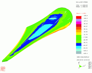
Before LM completes its leap from 54m to 61.5m, aerodyn Energiesysteme GmbH (Rendsburg, Germany) will become the long-blade leader for a time with a 56.5m/185 ft carbon/glass hybrid blade, on a rotor spanning 116m/380 ft. The blade features Tenax carbon (Tenax Fibers GmbH, Wuppertal, Germany) in the spar caps and blade roots and uses an epoxy matrix supplied by MGS Scheurfler/Bakelite (Stuttgart, Germany). SAERTEX (Saerbeck, Germany) fabrics and DIAB GmbH (Hemmingen, Germany) core materials are also employed. Blade weight is 15,700 kg/34,540 lb.
For this large size, aerodyn blade area leader Richard Schmidt reports that blade design was highly influenced by producability - ensuring that the process provided adequate access for layup, "especially with regard to carbon fiber laminate quality." The design also streamlined production by enabling parallel processing of blade components and segmented production, as well. "Due to the more expensive materials and the need to get the most out of the material, the level of analysis was far deeper than for a smaller kind of 'standard' blade," Schmidt notes. "We found the provision of simple and clear load paths important to enable a reliable design."
The hybrid blades are intended for an aerodyn-developed 5 MW turbine, the Multibrid, which will be deployed in the North Sea as part of Germany's first deepwater offshore project. Started for Pfleiderer Wind Energy GmbH (Neumarkt, Germany), the project was taken over in November 2003 by PROKON Nord Energiesysteme GmbH (Leer, Germany) as static testing of the first blade was drawing to a successful close. The first set of three blades should be delivered to a prototype turbine in May 2004.
When Is Carbon Worth It?
The lengths to which glass-only designs can be taken is a matter of some debate. GE Wind Energy's (Tehachapi, Calif., U.S.A.) longest blade (at 50.5m/166 ft for 3.6 MW turbines) is all glass, and LM has pushed the glass envelope farther than any other wind-blade manufacturer, with its 54P. "We expect [glass-only lengths] to be pushed even further in the future," contends LM's Nielsen. "The limit to length of blades made purely in glass fibers is not an absolute but depends on which blade properties are required by the specific turbine design." LM's long-blade designs include load-bearing skins, which Nielsen believes has helped them optimize glass-only designs.
At aerodyn, however, the current strategy is to use carbon/glass hybrids with rotor diameters greater than 100m (blades longer than about 48m). "In the past we have been involved in [carbon/glass hybrid] designs as small as 22m and up to 31m," Schmidt recalls. "They have not proven to be economical." LM's Nielsen agrees. "Using carbon is no virtue in itself if other less costly solutions are available."
On the other hand, Vestas Wind Systems A/S (Ringkøbing, Denmark) has introduced carbon into its relatively short (44m) V90-series blade. Carbon's greater stiffness reduces bending of the blades in high winds, allowing them to be positioned relatively close to the tower. "We have actually designed a turbine that, despite an increase in nominal output of 50 percent, weighs approximately the same as our V80-2.0 MW model," reports Lars Budtz, Vestas development manager. In fact, while the turbine heads (blades and hub) weigh about the same, individual blades are slightly lighter than the 39m/128-ft V80, despite being 5m/16 ft longer. Vestas also altered the airfoil geometry of the new blade, using a design developed in collaboration with Denmark's Risø National Research Laboratory. The new geometry improves energy production and reduces dirt loading on the leading edge. It also uses a curved back edge, a design specified by the company's optimization routines. Vestas will begin commercial production of V90 blades sometime this year.
Industry consultant Kyle Wetzel (K. Wetzel and Co. Inc., Lawrence, Kan., U.S.A.) estimates a potential weight reduction of 20 percent can be achieved by modifying an existing glass/epoxy 34m blade (for a 1.5 MW turbine) by incorporating carbon. But even with the weight reduction, he points out, "It's hard to do much more than break even on cost at 34m." Carbon improves edgewise fatigue resistance and, Wetzel concludes, this parameter becomes a critical design factor for blades longer than 42m to 45m.
A hard-and-fast cutoff length for incorporating carbon may not exist because of the many factors that contribute to cost-effectiveness. According to Jim Lyons, GE Wind's advanced technology leader, material costs need not be a critical factor in moving to carbon. "It's a lot more expensive material, but you use a lot less of it." In contrast, carbon fabrication requirements serve as both a motivation and a deterrent, aerodyn's Schmidt points out. "On one hand, you have to lay up far less material, which saves time and avoids processing problems [associated with thick laminates]," Schmidt says. "On the other hand, carbon fiber has much higher requirements with regard to processing accuracy. Alignment inaccuracies and void content have a much higher impact on the mechanical properties of a carbon laminate than they do on glass laminate properties."
Walter Musial, senior engineer at the U.S. Department of Energy's National Wind Technology Center (Golden, Colo., U.S.A.), agrees that fabricating with carbon is a less forgiving process. "Using conventional [wind-blade] manufacturing technologies, carbon isn't looking as good as it should," he states. "You can't take a mold that's designed for a glass blade and simply put carbon in it. It has to be re-engineered from the ground up." Any waviness introduced in the carbon affects the composite's compressive strength much more severely than comparable waviness in glass. Compressive strength is critical because of aerodynamic bending loads on the downwind side of the blade.
Wind energy consultant Dayton Griffin of Global Energy Concepts LLC (GEC, Kirkland, Wash., U.S.A.) adds that, as blade manufacturers move from hand layup to the more efficient vacuum infusion process, incorporating carbon becomes more difficult. "Blades tend to be thick and long, and the evacuation channels aren't great, leading to higher void content," he explains. "Any feature you put into a fabric that promotes resin flow also tends to create misalignments and waviness. Using high pressures creates similar problems. So then prepreg starts looking better." Furthermore, prepregging or stitching a fabric to ensure fiber alignment adds cost, making the economics less palatable.
To determine whether or not the effort and cost of incorporating carbon is worthwhile, Schmidt says, "The key is to look at the total system and not focus only on materials or individual components." For example, the high strength-to-weight ratio of carbon allows for smaller-diameter blade-root connections than a glass-only design does. "This means the hub and bearings also can be built smaller and lighter, [so that] altogether, the head weight of the turbine can be reduced," Schmidt explains. "This can reduce cost and makes installation easier."
GE Wind's Lyons envisions carbon/glass hybrids not only for longer blades on new turbines but also for potential retrofit blades to increase the rotor size of existing turbines. "Since the swept area is such a driver for the effectivity of the blade," he says, "carbon is an enabling technology."
Spar caps and blade roots, the most highly loaded areas of the blade, are the obvious areas for carbon to serve existing blade designs. But Wetzel is also researching completely new blade designs. "The industry has moved so rapidly - from 300 kW to 3 MW turbines in 10 years - there's been little opportunity to start with a blank piece of paper and ask what an optimized design would look like," he says. Free to create contours, aerodynamics and structure specifically for a carbon-fiber composite, he believes blade engineers could arrive at a radically different design. The blade likely would be more slender, with a thinner profile. Furthermore, "the ratios could change so that carbon may even predominate," he speculates, "with small amounts of glass for fatigue resistance in strategic places or where you need bulk for mounting, such as at the blade root."
Twist coupling compresses costs
Another use of carbon that could improve blade performance, and therefore lower energy costs, is in a design concept called bend-twist coupling. This property exploits a characteristic unique to fiber-reinforced materials, the ability to produce a non-symmetric laminate. Most composites balance the fiber loading at a given angle with the same loading at the opposing angle; +45° and -45°, for example. When these balanced laminates are subjected to an axial bending force, they respond uniformly along their axes. When an unbalanced laminate - where fibers at a given angle are not matched by opposing fibers - is subjected to that same axial bending force, it will translate some of the force to the off-axis direction. As a result, the laminate will twist around that axis.
Twist coupling addresses two of a wind blade's functional design issues. First, wind turbines must have overspeed protection to prevent the generator from running above its operating range and to keep power generation relatively smooth. Currently, large turbines use pitch control, which actively detects high winds and rotates the blade angle to shed the excess. Twist coupling is not expected to change the angle of attack as much as pitch control does, so the latter is still necessary. However, twist coupling improves power regulation and energy efficiency by enabling the blades to respond to gusts - sudden, transient events to which the pitch actuator is too slow to respond effectively. Generator efficiency improves as the power input is smoothed, and twist-coupling serves this function.
Second, especially because the blades of nearly all commercial wind turbines are positioned in front of the hub, they are designed to withstand high head winds or gusts that would bend them toward the tower. Current designs use "pre-bent" geometries and feature high levels of built-in flapwise stiffness to resist bending and reduce fatigue. In addition to mitigating the load created by sudden gusts, twist-coupling also will reduce fatigue by allowing each blade to respond individually to the particular loads it experiences. (Pitch control for individual blades is complex and currently cost-prohibitive for most turbines, although Vestas' V90-3MW turbine may be fitted with it.) As a result, twist-coupled blades may perform better using less material and, with less pre-bending, may be easier to transport by truck, as well.
Twist coupling today is still confined primarily to the government-funded research arena. Commercial development is at least three-to-five years in the future. Sandia National Laboratories (Albuquerque, N.M., U.S.A.) commissioned initial studies of twist coupling in a 9m/30 ft blade, awarding contracts to two teams, which have taken radically different approaches to incorporating bias carbon fibers for the coupling. One team, led by GEC, with members TPI Composites (Warren, R.I., U.S.A.) and MDZ Consulting (Kemah, Texas, U.S.A.) will place the bias fibers in the blade skin. The other, composed of Wetzel and Wichita State University (WSU, Wichita, Kan., U.S.A) will place the bias fibers primarily in the spar caps.
GEC's Griffin explains that with carbon in the skins, the glass-reinforced spar will twist when the skins want to, contending that bias carbon in the spar caps compromises the spar's stiffness because the biased continuous fibers do not run the entire length of the spar. Rather, most fibers begin and/or terminate at spar cap edges. Therefore, stresses must traverse matrix at the fiber ends. Wetzel counters that for large blades, carbon's principal promise is greater stiffness than glass for a given cost of material, so the most cost-effective place to employ it is in the spar caps. Even bias carbon in the caps will be stiffer than an all-glass spar cap. Using bias carbon in the skins presents challenges with shear strength, which he believes is the critical parameter for twist-coupled blades. "You have to have a certain amount of biaxial material in the skin to maintain torsional rigidity and stability," he says. "The wind industry doesn't have reliable allowables for shear strength." As a result, the carbon bias fibers would be an addition to the skin materials rather than a replacement. And this, Wetzel contends, is not cost-effective.
To accurately align the bias fibers, the GEC team is using a stitched triaxial fabric from SAERTEX USA LLC (Mooresville, N.C., U.S.A.) with carbon in the axial direction and glass at +/- 45°. For the prototype, GEC will orient the carbon at 20°. As a result, the glass angles will be +65° and -25°, but Griffin reports that this orientation still adequately manages shear loads. Wetzel has also turned to SAERTEX, sourcing a stitch-bonded fabric with glass and carbon in the axial direction and carbon oriented at 20°.
Griffin's team is continuing its work under Sandia and will finish twist-coupled prototypes as this article goes to press, with testing to follow late in the year. Wetzel's team, however, has received an SBIR grant from the U.S. Department of Energy for research on a much larger 34m/112 ft twist-coupled blade. Wetzel expects to build a 34m demonstrator blade later this year. Both teams are also researching conventional designs, using carbon to lighten the structures.
A new spin on blade speed
Beyond the issues of length and carbon/glass hybrids, a key objective at GE Wind is to increase the allowable rotational speed of the turbine. To keep noise levels acceptable, wind industry regulations set a maximum tip speed (currently 70m/sec for land-based turbines in the United States, for example). "If you can spin faster," Lyons contends, "you can drive a cost-of-energy reduction, but you need to control acoustic noise."
Although GE Wind's entry into the wind energy market was comparatively recent, with its purchase of Enron Wind in June 2002, the company is leveraging its knowledge base from other markets to redesign blades for quieter operation. "As we formed the wind business," notes Lyons, "we've been taking a look at all our areas of expertise." The company's polymer business, for example, could eventually benefit wind blades. Currently of interest, he reports, are the company's computational fluid dynamics (CFD) tools and its staff experience with gas turbines and jet engines, developed, for example, during the design and fabrication of composite fan blades for the GE-90 engine. Many members of the GE-90 fan blade team are now working on improvements to trailing edge and tip shapes, which are expected to minimize air turbulence, improve efficiency, and decrease noise at higher speeds. "Instead of taking the design allowables provided by the industry," Lyons suggests, "we can go to them with a greater understanding of what can be done."
Testing the economic winds
Modification of existing glass designs is clearly nearing its practical limit and more dramatic changes may be inevitable. But to abandon conventional designs rather than use them as a baseline may require deeper pockets than most current wind-energy players can provide, one industry observer speculates.
Several factors, however, favor capital reinvestment. The global market base continued to grow in 2003, with 23 percent (5,381 MW) and 36 percent (1,687 MW) increases, respectively, in Europe and the U.S. alone. Further, the cost of wind-generated electrical power has achieved near-parity with that of energy derived from fossil fuels. The American Wind Energy Assn. (AWEA, Washington, D.C., U.S.A.), for example, reports that energy from state-of-the-art wind turbines costs 3 to 6 cents/kWh (USD), compared to about 3.8 to 6 cents/kWh for fossil-fuel combustion turbines.
But not all winds blow fair. AWEA has decried the U.S. Congress' recent failure to renew the Production Tax Credit, an incentive the association views as vital to continued growth. In Europe, says Corin Millais, chief executive of the European Wind Energy Assn., "We face maturing markets in the three leading countries - Germany, Spain and Denmark - which account for 84 percent of the total wind power capacity installed in EU-15 by the end of 2003. These figures highlight a weakness in the market that needs to be corrected."
Still, wind has become cost-competitive with fossil fuels on the strength of glass-only designs. Waiting in the wings are innovations still in their infancy (carbon-driven and otherwise) that hold the promise of wind power supremacy - an opportunity those with deep pockets are unlikely to ignore.
Related Content
Recycling end-of-life composite parts: New methods, markets
From infrastructure solutions to consumer products, Polish recycler Anmet and Netherlands-based researchers are developing new methods for repurposing wind turbine blades and other composite parts.
Read MoreCollins Aerospace to lead COCOLIH2T project
Project for thermoplastic composite liquid hydrogen tanks aims for two demonstrators and TRL 4 by 2025.
Read MoreECOHYDRO project to enable recyclable composites for hydrogen storage
With the involvement of two schools from the Institut Mines-Télécom, the 4-year project aims to improve the intrinsic properties of a composite material based on Elium via four concrete demonstrators.
Read MoreInfinite Composites: Type V tanks for space, hydrogen, automotive and more
After a decade of proving its linerless, weight-saving composite tanks with NASA and more than 30 aerospace companies, this CryoSphere pioneer is scaling for growth in commercial space and sustainable transportation on Earth.
Read MoreRead Next
Big Blades Cut Wind Energy Cost
Rapid growth rate of composite-intensive conversion systems drives market competition and innovation.
Read More“Structured air” TPS safeguards composite structures
Powered by an 85% air/15% pure polyimide aerogel, Blueshift’s novel material system protects structures during transient thermal events from -200°C to beyond 2400°C for rockets, battery boxes and more.
Read MorePlant tour: Daher Shap’in TechCenter and composites production plant, Saint-Aignan-de-Grandlieu, France
Co-located R&D and production advance OOA thermosets, thermoplastics, welding, recycling and digital technologies for faster processing and certification of lighter, more sustainable composites.
Read More
