Carrier-capable, all-composite external fuel tank
Legacy product positions builder for a shot at an F-35 contract.
Design Results:
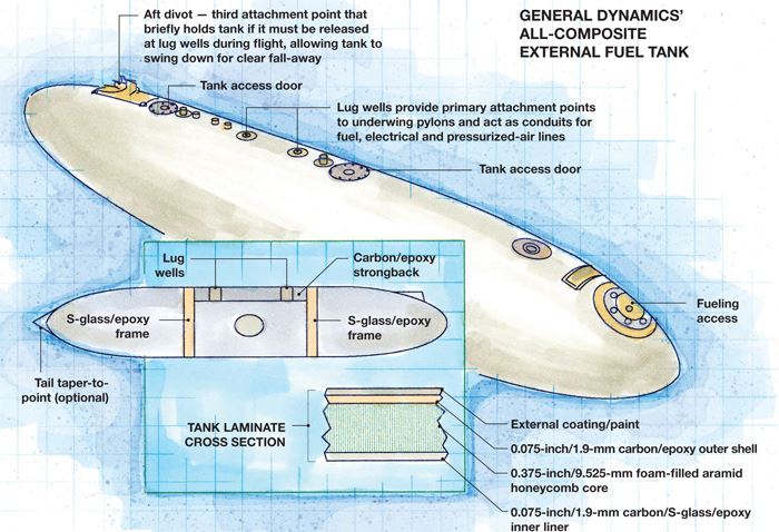
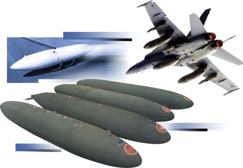
- An inner liner of S-2 Glass impregnated with a proprietary epoxy formulated for compatibility with the filament-winding process is able to resist continuous exposure to jet fuel.
- A honeycomb core made of urethane foam-filled Kevlar adds structural stiffness needed for aircraft carrier survivability requirements.
- The tank’s carbon-fiber/epoxy filament-wound “box beam” provides internal structural support and attachment points to the jet via lug wells in the outer shell.
When the U.S. Navy and Air Force commissioned the development of the first external fuel tanks in the 1960s to extend the mission range of its fighter aircraft, steel, aluminum and other metals were still the materials of choice. The first external fuel tanks used by McDonnell Douglas, now part of The Boeing Co. (Chicago, Ill.), were all-metal. They included the 600-gal/2,271L tank used on the F-4 Phantom and the 300-gal/1,136L tank used on the A-4 Skyhawk.
Unfortunately, it took a catastrophe to alert designers to the potential advantages of composite materials. The aircraft carrier USS Forrestal (CV 59) was deployed off the coast of Vietnam in July 1967 when a missile inadvertently launched from another fighter jet hit an A-4 jet parked on the flight deck. The A-4’s external fuel tank ruptured, spreading fuel and fire across the deck. The fire quickly engulfed other aircraft, and before the fire was doused, more than 100 seamen died in one of the worst accidents in U.S. military history.
In the tragedy’s wake, the Navy commissioned a team to investigate and recommend ways to improve survivability in the event of a carrier deck fire. The investigation exposed, among other things, the fallibility of all-metal external tanks, especially with respect to ballistic piercing and rupture upon impact with a hard surface. Subsequently, the Navy mandated a more stringent set of survivability and performance requirements for aircraft carrier environments. These included a battery of tests to confirm that a tank has the ability to meet survivability and in-flight load standards. Several of the tests were severe, including ejection of a full tank onto a hard surface, projectile impact, and bonfire resistance. All of these tests required that the tanks maintain a specified structural integrity that would minimize damage and the possibility of a spreading fire.
In the mid-’70s, General Dynamics Armament and Technical Products (GDATP, Lincoln, Neb.) partnered with McDonnell Douglas to design an external fuel tank to meet these standards.
Hybrid design enables early tank
By late in the decade, the two companies had built a hybrid composite/metal tank for the F/A-18 Hornet fighter jet. The decision to go with a hybrid construction, rather than an all-composite tank, was based largely on the fact that, at the time, a jet-fuel-resistant resin system had yet to be tested and qualified.
The tank comprised an internal liner of aluminum, overwrapped with a sandwich construction. The inner and outer skins of the sandwich were laid via filament winding, using S-glass/epoxy yarn. The core was urethane-foam-filled honeycomb made of Kevlar aramid, developed by what is now DuPont Protection Technologies (Richmond Va.), and a filament-wound outer shell of S-glass fiber yarn. McDonnell Douglas supplied the aluminum tank, and GDATP manufactured the outer skin and core. The tanks came in two sizes: a 330-gal/1,250L cylindrically shaped unit and a 315-gal/1,192L, elliptically shaped component. Although GDATP stopped producing these tanks in the 1980s, Cyclone Ltd. (Karmiel, Israel), a subsidiary of Israel-based Elbit Systems, still manufactures a version of this hybrid tank, based on the original design.
Following this successful demonstration of composites’ capability as an outer-skin material in a hybrid tank, McDonnell Douglas and GDATP investigated in the mid-’80s the possibility that an all-composite external tank for the F/A-18 could be built to reduce the mass of the metal-lined hybrid tank.
Emulating an auto breakthrough
At that time, aerospace engineers were drawing inspiration from the automotive industry, where the first all-plastic gas tanks had been introduced in high-density polyethylene (HDPE). However, HDPE couldn’t be considered for jet tanks, says Rick Rashilla, GDATP’s senior manager of business development: “In addition to compatibility with long-term exposure to jet fuel, the resin had to be compatible with the fabrication process.” HDPE was not. It also did not meet the weight goal. And it posed problems in terms of a good bond to the honeycomb core. GDATP faced more severe survivability requirements (takeoff, inflight and landing loads) as well as greater impact risks with the outboard tank than would be expected with an inboard automotive fuel tank. So engineers were presented with the formidable challenge of finding a resin that would be tough enough to withstand continuous contact with jet fuel and withstand severe operational conditions yet meet weight and manufacturability requirements.
After about a year of testing, GDATP developed an epoxy system that met all requirements. “The trick we pulled off was finding a multipart, high-elongation epoxy resin system that would allow us to manufacture a glass-fiber, filament-wound inner liner that acts as a fuel permeation barrier,” says Rashilla. S-glass was selected for the liner because “it provides adequate structural support at a lower cost than carbon fiber.”
The core of the first all-composite tank is similar in basic design to the core of the hybrid tank that preceded it — a foam-filled, honeycomb core made of aramid. However, the outer shell comprises intermixed layers of filament-wound HexTow AS4 PAN-based carbon fiber, supplied by Hexcel Corp. (Stamford, Conn.) and S-2 Glass, which was codeveloped by Owens Corning (Toledo, Ohio) and the U.S. Air Force. In 1998, S-2 Glass became a trademarked product of the Owens Corning and Groupe Porcher Industries (Le Grand Lemps, France) independent joint venture Advanced Glassfiber Yarns, now known as AGY LLC (Aiken, S.C.).
Because the epoxy for the liner was developed primarily to meet criteria for fuel resistance, GDATP formulated a different grade of epoxy that is more suitable for the primarily structural function of the outer shell. The tank also was designed with access doors and additional layers of fabric for reinforcement in the areas around lug wells (cylindrical, sleeve-lined joints), which offer attachment points for pylons on the plane’s bomb rack.
By the late 1980s, all-composite 480-gal/1,817L external fuel tanks for the F/A-18 were in production. The first customer, the Royal Canadian Air Force, used the tanks on its fleet of CF/A-18s. GDATP later manufactured (but did not design) a 230-gal/871L version of the tank for the U.S. Army’s UH-60 Black Hawk and AH-64 Apache helicopters. The all-composite tank was approximately 30 percent lighter than the hybrid tank. The inner liner is wet wound over a steel mandrel. Epoxy-impregnated S-glass is wound to a layer thickness of 0.075 inch/1.9 mm. Then a 0.375-inch/9.53-mm layer of foam-filled aramid core is attached to the inner liner, and the two layers are cured together in an oven. After cure, the inner shell/core is cut in half circumferentially and removed from the mandrel. A square-shaped box beam formed from two glass-fiber arms or frames and a carbon fiber/epoxy filament-wound “strongback” are installed inside the tank to provide internal structural support and external attachment points (see illustration, at top right). The top of the strongback is designed with a radius identical to that of the inner shell, and it fits flush with the inside of the shell. Circular lug wells shaped into the top of the strongback act as receiving joints for the aircraft pylons and as conduits for fuel, air and electrical lines. The two sections are rejoined with an adhesive bond, then a 0.075-inch/1.9-mm-thick layer of epoxy-coated S-glass and carbon fiber is wound around the inner liner and core to form the outer shell. The entire assembly is placed in an oven to facilitate curing of the outer shell.
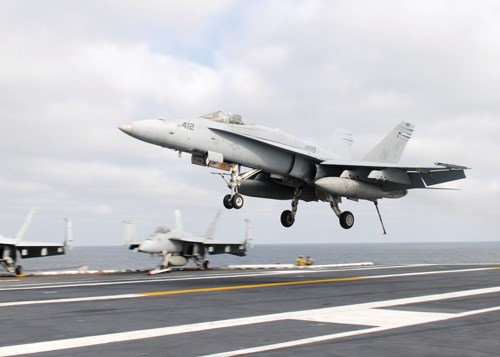
The all-composite design piqued the interest of the U.S. Navy, which still used the hybrid tank. Its design met general aircraft carrier survivability requirements, but GDATP was asked to qualify it for the extreme load requirements of carrier-based F/A-18s during catapult-assisted takeoff and tailhook arrestment during landing. To compensate for these loads, GDATP added composite material in certain areas, such as the lug-well attachment points. This enabled qualification of an otherwise similar 480-gal/1,817L external fuel tank for the carrier jets in the early 1990s.
GDATP currently provides service and stocks parts for its tank, but no longer manufactures it. However, General Electric manufactures a similar tank.
Project-ready design capabilities
GDATP’s modeling and simulation software is built on a commercial software platform from ANSYS (Canonsburg, Pa.). But it has been customized, Rashilla says, making it capable of modeling the effects of loads and stresses on iterations of in-tank design parameters, including different fibers, thicknesses and orientations. Modeling can be carried out quickly, he adds, with the aid of special programming features. “In metals or lay-up methods of manufacturing, the materials are usually well known and an engineer can look up the material properties of, say, 6061 P6 aluminum in a handbook.” But because GDATP formulates its own materials from base fibers and proprietary resins, Rashilla explains, the company must determine, via testing, the A- and B-basis allowables of those materials. In simple terms, A- and B-basis allowables refer to the statistical certainty one can assign to a given set of test data. Customers decide whether a material used in a specific application must meet A-basis requirements, which require more extensive test data, or the less-stringent B-basis requirements.
Given this state of readiness, Rashilla says GDATP’s next major design/manufacturing opportunity for an all-composite external fuel tank is likely to be the F-35 Lightning II. He expects an external tank will be built for the new jet at some point but reports that funding has yet to be approved. “The survivability requirements for the tank used in the carrier variant of the F-35 will be essentially the same,” Rashilla says. “We hope to be able to apply the lessons we learned on our F/A-18 tank design to that project.”
Related Content
Manufacturing the MFFD thermoplastic composite fuselage
Demonstrator’s upper, lower shells and assembly prove materials and new processes for lighter, cheaper and more sustainable high-rate future aircraft.
Read MoreSulapac introduces Sulapac Flow 1.7 to replace PLA, ABS and PP in FDM, FGF
Available as filament and granules for extrusion, new wood composite matches properties yet is compostable, eliminates microplastics and reduces carbon footprint.
Read MorePlant tour: Albany Engineered Composites, Rochester, N.H., U.S.
Efficient, high-quality, well-controlled composites manufacturing at volume is the mantra for this 3D weaving specialist.
Read MoreNatural fiber composites: Growing to fit sustainability needs
Led by global and industry-wide sustainability goals, commercial interest in flax and hemp fiber-reinforced composites grows into higher-performance, higher-volume applications.
Read MoreRead Next
Developing bonded composite repair for ships, offshore units
Bureau Veritas and industry partners issue guidelines and pave the way for certification via StrengthBond Offshore project.
Read MorePlant tour: Daher Shap’in TechCenter and composites production plant, Saint-Aignan-de-Grandlieu, France
Co-located R&D and production advance OOA thermosets, thermoplastics, welding, recycling and digital technologies for faster processing and certification of lighter, more sustainable composites.
Read More“Structured air” TPS safeguards composite structures
Powered by an 85% air/15% pure polyimide aerogel, Blueshift’s novel material system protects structures during transient thermal events from -200°C to beyond 2400°C for rockets, battery boxes and more.
Read More


.jpg;maxWidth=300;quality=90)


