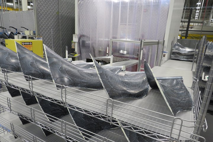
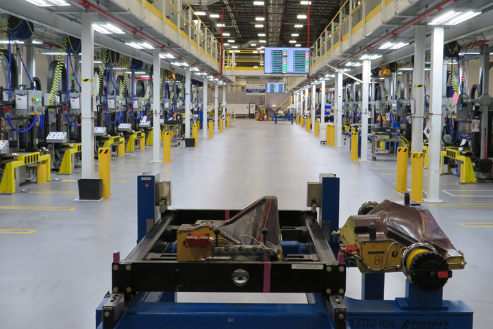
Figure 1. Albany Engineered Composites jointly operates, with Safran, three facilities to manufacture fan blades, fan cases and spacers for CFM International’s LEAP aircraft engine. The blades shown here, freshly fabricated via resin transfer molding (RTM), are in Albany’s Rochester, N.H., U.S. plant, the company’s largest for case and blade production. Other Albany/Safran plants are in France and Mexico. Photo Credit, all images, Albany Engineered Composites
Given all the talk about the challenges associated with meeting high-volume manufacturing requirements in next-generation composite aerostructures, it’s easy to forget that there already are aerocomposite programs that demand a robust level of automation, industrialization and quality.
Such is the case at Albany Engineered Composites (AEC) in Rochester, N.H., U.S., where the company has been fabricating, since 2013, carbon fiber composite fan cases, fan blades (Fig. 1) and spacers for all variants of the LEAP aircraft engine, manufactured by CFM International (Cincinnati, Ohio, U.S.), a joint venture of General Electric (Cincinnati) and Safran Aircraft Engines (Courcouronnes, France). AEC is the sole source manufacturer of the fan cases, fan blades and fan blade spacers.
Co-developed and designed by Safran for the single-aisle aircraft market, the LEAP engine is targeted toward aircraft manufactured by Airbus, Boeing and Comac, and has become the de facto standard for narrowbody aircraft propulsion. The LEAP-1A variant, offering 24,500-33,000 pounds of thrust, is one of two engine options available for the Airbus A320neo Family (the Pratt & Whitney GTF engine is the other). LEAP-1B (23,000-28,000 pounds) is the sole engine option for the Boeing 737 MAX aircraft. LEAP-1C (27,980-30,000 pounds) is the sole engine option for the Comac C919. Each LEAP engine features 18 carbon fiber composite fan blades (Fig. 1) rotating inside a carbon fiber composite fan case.
Safran, at its December 2022 Capital Markets Day, said the LEAP engine (all variants) has a 72% share of the global narrowbody market and a 60% market share on the A320neo Family. Further, Safran reported an order backlog of 10,300 LEAP engines, which represents a staggering 185,400 fan blades, making this engine platform the largest composite fan blade consumer in the world.
Compounding the challenge of manufacturing volume is that of quality. A fan blade is vitally important and is the primary structure to an aircraft engine’s operation for obvious reasons; as such, blade failure — particularly a blade-out condition — must be exceptional and rare. This combination of manufacturing volume and quality is rare in the aerocomposites industry, but it is also a bellwether of what’s to come.
When CW first visited AEC in Rochester in 2013, the company was just getting its manufacturing operations started for the LEAP program. Today, a decade later, AEC’s Rochester facility is fully industrialized for high-volume, high-quality composites fabrication that has positioned the company well to be a major fabricator in the aerospace market. In our latest visit, CW got to see firsthand how the company achieved this transition. Lessons learned along the way will be instructive for the entire aerospace composites supply chain.
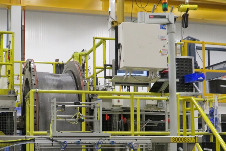
Figure 2. Albany manufactures three variants of cases and blades for the LEAP engine — one for Airbus (1A), one for Boeing (1B) and one for Comac (1C). Dimensions vary moderately from variant to variant, but the fan case for each is ~2 meters in diameter. Shown here is a woven fan case preform being wound onto a mandrel, prior to RTM.
Three parts, three plants
It’s important to understand a couple of things about AEC’s Rochester facility. First, it’s not home to AEC only. Safran, as the customer, operates about a third of the 345,000-square-foot plant and takes direct delivery of all product AEC manufactures for the LEAP program.
Second, this is not the only AEC/Safran facility fabricating fan cases and blades for the LEAP program. There are two other similar but smaller facilities — one in Commercy, France (100,000 square feet) and one in Querétaro, Mexico (70,000 square feet), also jointly operated with Safran. Each facility is AS9100-certified and together the three plants employ about 675 people.
Beyond the LEAP program, AEC also operates facilities in Boerne, Texas, U.S. (170,000 square feet), Salt Lake City, Utah, U.S. (652,000 square feet) and Kaiserslautern, Germany (55,000 square feet). AEC employs about 1,800 people globally.
For LEAP, however, the Rochester facility is the flagship operation. It also fabricates all three of the composite parts in the contract, in annual quantities inversely proportional to part size: fan cases (1,500), fan blades (10,000), spacers (30,000). One LEAP shipset out of the Rochester facility comprises one fan case, 18 fan blades and 18 spacers.
The Rochester plant is also home to fabrication of the 3.8-meter-diameter fan case for the GE9X engine, manufactured by GE Aerospace (Cincinnati) for the Boeing 777X. With a thrust of 105,000 pounds, the GE9X is the largest and most powerful commercial aircraft engine in the world.
The plane it’s made for, however, is not yet flight-certified and is not expected to enter into service until 2025. Further, the commercial aerospace industry is trending away from the widebody aircraft architecture on which the 777X is based. Still, the GE9X fan case represents for AEC the scale and efficiency that has been achieved at Rochester.
Regardless of the part, all manufacturing at the Rochester facility, which employs about 275 people, revolves around two core processes: Customized, highly engineered weaving of 3D continuous fiber reinforcements, and resin transfer molding (RTM) of those fabrics in highly specialized tooling systems.
AEC describes itself as the world leader in 3D woven composites, attractive because of the cascading benefits they provide: through-thickness reinforcement, multilayer interlocking preforms, integrated structures, contourability, near-net shape preforming, high automation and minimal waste.
Brent Stevenson, VP engineering and technology, emphasizes the benefits of 3D weaving in the fan cases: “With 3D weaving, we can offer continuous fiber in the axial direction and continuous fiber in the radial direction. That’s what is unique about our technology, combined with the fact that you have material in that third dimension holding it together. All three of those are coming together to create a really unique preform technology.”
CW’s visit focused on understanding how weaving and RTM have been optimized for high-rate aerospace manufacturing.
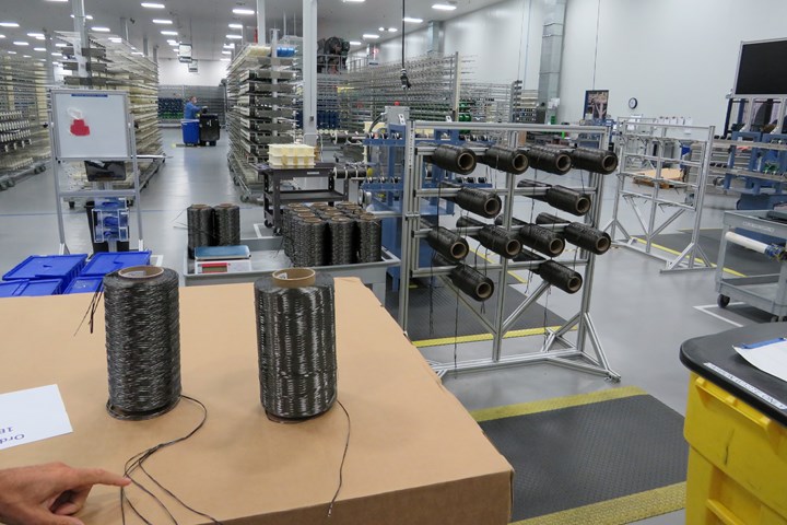
Figure 3. One of Albany’s core technologies for fan case and blade production is 3D weaving. Each loom that performs the weaving is fed by thousands of tows or yarns of carbon fiber. Shown here is the carbon fiber preparation area, where color codes are used to denote fiber type and format prior to creel delivery to the looms.
Fan cases
CW’s tour of the Rochester facility, led by Réjean Lavallée, director of operations at the facility, starts with the largest composite part on a LEAP engine. The fan cases for the LEAP variants are similar but not identical, with slight differences in architecture and diameter depending on engine thrust — the larger the thrust, the bigger the fan case. However, each variant is ~2 meters in diameter, 750 millimeters wide and weighs significantly less than comparable metallic designs, and each is fabricated following the same procedures.
The first step, and CW’s first tour stop, are five massive weaving machines producing complex carbon fiber fabric preforms in widths that match the width of the fan case. These are Jacquard-type looms, weaving a dry carbon fiber. The loom is designed to enable AEC to taper the fabrics to vary the thickness as needed to accommodate fan case architecture.
The loom is fed from the rear by more than 2,000 spooled tows that comprise multiple types of carbon fiber yarns. The complexity of weaving at AEC is measured by a variety of factors, including preform architecture, shape and length. A complete fan case preform uses tens of thousands weft fibers and measures approximately 80 feet long.
Much of the manufacturing efficiency that AEC has gained over the last decade revolves around the weaving process. Lavallée says fan case weaving speed is four times faster now than it was in 2013. Other metrics have been improved as well: The process is more stable and consistent, machine utilization is higher, scrap rate has been reduced to 2.5% (and going down) and touch labor has been significantly reduced.
This increased efficiency is not trivial. In fact, AEC points to machine utilization throughout all operations as the one metric that has driven the company’s ability to ramp up and meet the rate requirements of the LEAP program. “When that became the metric,” says Ray Ringleb, senior director of business development, “it just changed everything.” (See sidebar on p. 42 for more about AEC ‘s asset utilization strategy.)
After a fan case preform is woven, it then moves to the winder for placement on the mandrel (Fig. 2). The winder wraps the woven preform around the IML fan case mold. “After weaving, the preform is rolled up and then unwound under tension while using laser alignment assistance to make sure proper positioning into the tool,” Lavallée says.
It is apparent, even at this early stage, that AEC’s operations depend greatly on advanced technologies to manage preform quality, placement and alignment. “You will see a lot of process monitoring throughout the plant,” says Stevenson. “Laser alignment, cameras, data boards pulling information right off the machines, driving that operational excellence because the production rate requires it. Because again, as we learned, small perturbations can get out of hand very quickly. We have to manage process control very carefully.”
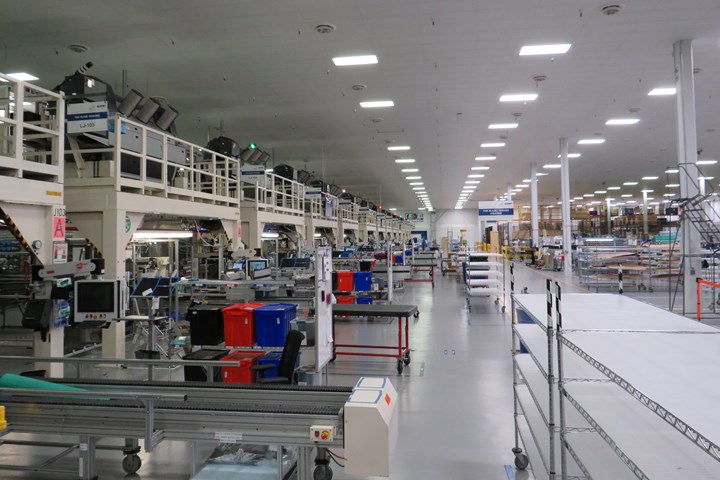
Figure 4. The highest volume product Albany manufactures for the LEAP program is the fan blade. Each engine turns 18 blades, and with an order backlog of 10,000+ engines Albany has 185,000+ blades to fabricate. Shown here are the looms in the Albany Rochester facility weaving the complex 3D preforms for the blades.
Lavallée says it takes AEC several hours to wind the 80-foot preform onto the tool. Once the tool is fully assembled, it is then transferred to an oven and prepped for RTM. Resin is delivered to each tool by the system through multiple injectors. The resin system used is a toughened epoxy system.
As he explains injection and cure, Lavallée notes that AEC is avidly pursuing technologies to automate the process as much as possible to remove the human element. “We really understand the key process parameters,” he says. “And we are systematically working through all the processes to remove any source of variation in those parameters by adding technology and minimizing touch labor.”
After cure, fan case dimensions are verified and documented. This is particularly important for Safran, says Stevenson, which requires notification if anomalies are detected.
“At these rates, if all of a sudden we have a slip of even just 30-thousandths of an inch,” he says, “Safran may need to adapt their machining and they need to know that’s coming. Then, either we need to correct that or Safran needs to make an adjustment to its machining. These early warning signs are critical.”
Delivery of fan cases — and all other LEAP products — is done quickly, given that Safran is co-located in the Rochester facility with AEC. Safran’s operations exist just beyond our view and are separated from AEC’s space in the factory by a modest partition that is testimony of the close working relationship that the two companies enjoy.
Lavallée says that Safran, when it receives a fan case or blades, performs several finishing operations to prepare the parts for engine integration. These include machining, drilling, painting and attaching the leading edge (fan blades).
AEC’s relationship with Safran is close, physically within the plant and as a business partner. Michael Dill, senior vice president of marketing and business development, notes, “We have found Safran to be a great partner. They recognize our expertise and let us manage that as we see fit. It’s been a great working relationship over the years.” AEC and Safran announced in 2021 that their development partnership has been renewed until 2046.
Fan blades, spacers
Leaving fan cases, the tour moves to fan blade and spacer fabrication, the manufacturing operation that consumes the most space in the Rochester facility. Here, product size decreases, but the volume of all else — materials, weavers, RTM systems — increases substantially.
Figure 5. After each fan blade preform is woven, it is transferred to a matched metal mold like the one shown in the foreground here. Laser projectors verify proper preform placement before the mold is closed and transferred to one of 25 RTM presses (background) for resin injection. The toughened epoxy resin system is the same as that used in the fan cases.
The first thing we see is the raw material preparation area for the weaving operation (Fig. 3). This features multiple racks of color-coded creels holding carbon fibers in a variety of formats, ranging from single tows to multiple tows twisted into yarns. The colors on each creel signal to operators the type and format of the fiber; these colors, in turn, correlate to colors on the looms, signaling to operators where creels should and should not be used.
Color, it turns out, is a big part of AEC’s manufacturing strategy and helps operators easily and quickly match up materials with equipment. Stevenson reminds us that the processes and procedures used in Rochester are not confined to Rochester. They must be followed in the Mexican and French plants as well.
“The challenge is to produce product in three plants in three different cultures,” Lavallée says. “It really made us understand what needed to be done to standardize operations so that we can make the same parts in three different places to the same specifications. Using color is one way to do that.”
Passing through material prep, we enter an impressively long and wide array of looms (Fig. 4). The vast majority of these looms are devoted to the weaving of fan blade preforms; one loom produces spacer preforms. Each fan blade loom here is fed by more than 3,500 tows of carbon fiber and each preform requires thousands of weft tows.
Like the fan case looms, weaving is programmed to produce fan blade preforms with a highly specific shape and architecture to meet the design requirements of the application. One notable difference is that fan blade design features a thick root section that tapers in two directions to a relatively thin tip. The weaving process must accommodate this tapering to achieve a near-net shape preform.
Lavallée says a single loom can weave multiple blade preforms in 24 hours. Further, similar to the fan case looms, efficiencies in the fan blade looms have increased over the last decade, allowing AEC to more than double throughput.
Lavallée says each loom, here and in the fan case area, is equipped with a variety of automated tools designed to provide in-process quality inspection. This includes automated visual detection technology to look for broken fibers and broken tows, which Lavallée notes are not definitionally problematic.
Stevenson expands on this idea: “This [inspection] process has become very stable, such that we very rarely are compelled to perform rework. More often, we see gradual process deviation over time, which we correct.”
A fan blade preform emerges from the loom as a very dense, near-net shape blade-like 3D structure. The preform is very thick and fully 3D at the root, and then tapers down in thickness toward the edges and tip. Also, the preform is not fully carbon fiber; there are other fibers strategically integrated to provide process and performance advantages.
At this point, Lavallée says, there is some excess material on the preform. This is currently removed via automated and manual trimming processes. After trimming, the preform is conveyed, lying flat, to the next step in the manufacturing process, which is RTM.
The RTM area comprises banks of injection units, organized in two parallel rows (Fig. 5). Here, preforms are manually placed into the female half of a matched metal mold (see foreground, Fig. 5). Overhead laser systems guide manual preform placement and location.
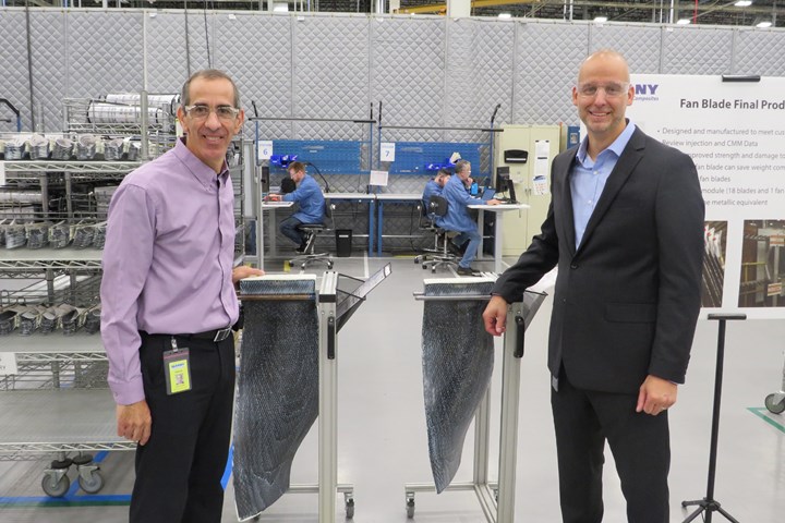
Figure 6. Réjean Lavallée (left), director of operations, stands with Matt Chapman, incoming director of operations, at the Albany facility in Rochester. They are standing with two LEAP fan blades that have just come out of an RTM press and will soon be delivered to Safran, which operates the plant with Albany. Safran’s operations are performed on the other side of the white partition in the background.
Next, the mold is transferred to a a drying process. This, says Stevenson, is needed to remove residual moisture from the fibers, which causes the preform to stiffen. It’s in this condition that the mold is then closed and manually transferred into a preforming process.
Then, it’s on to an injection unit where the same toughened epoxy resin matrix as that used in the fan cases is injected into the preform. After cure, blades are trimmed to remove flash, loaded onto carts and transferred to Safran (Fig. 6).
As we leave the RTM area, we pass an automated resin loading system AEC uses to create the recipe for the LEAP products. Lavallée notes that a slightly different combination of resins is required for the 1A and 1B fan blades as well as the 1A and 1B spacers. “Process improvement through automation of this stage of the process continues to be a focus improvement area for AEC,” Lavallée states.
GE9X fan case, R&T
Leaving LEAP fabrication behind, we are led into a separate building in Rochester where many of the same technologies are used to fabricate the massive fan case for the massive GE9X engine. If fabrication of the LEAP fan case is daunting in its scale and complexity, then fabrication of the GE9X fan case for the Boeing 777X program is otherworldly.
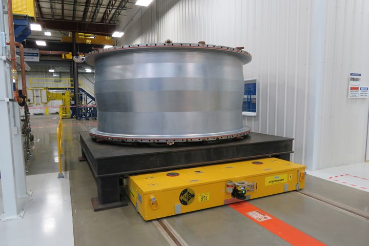
At 3.8 meters in diameter, it’s about the size of a 737 MAX fuselage (Fig. 7). Its preform is more than 60 meters long, 1.6 meters wide and requires more than 4,000 warp ends. The GE9X fan case mold weighs 80 tons and uses multiple injectors. The resin doesn’t even begin to harden until 30 minutes after injection because viscosity is kept so low for fiber wetout.
The only uncertainty here is what the future holds for the 777X and, by extension, the GE9X engine itself. The migration of commercial aerospace away from long-haul widebody jets and toward narrowbody architectures, combined with the slow recovery of international travel following COVID, makes the future of the 777X cloudy as best.
AEC is producing only a handful of GE9X fan cases a year until the 777X enters service in 2025. In the meantime, AEC takes pride in the fact that it has proved it has the technical muscle to scale up RTM to produce next-gen aerostructures.
Figure 7. Although Albany’s Rochester facility is dominated by LEAP production, the company operates a separate building for production of the GE9X fan case, the mandrel for which is shown here. The GE9X is the largest aircraft engine in the world and has a fan case 3.8 meters in diameter. Albany uses the same materials and processes (woven carbon fiber, RTM) to make this fan case, although production is limited as the launch aircraft for the engine, the Boeing 777X, has not yet entered service.
The final stop on CW’s tour of the Rochester facility is R&T, where it’s obvious that AEC is highly focused on improving what it already does well, and on developing technologies that will allow the company to seize new opportunities.
Stevenson says AEC’s evolution into high-volume composites manufacturing “has enabled us to capitalize on investments and build efficiencies that will broaden the application for 3D woven composites.”
Equipment in R&T reflects what we saw in the production area: multiple injection units, a fan case winder, a fan blade preforming cell, an oven and a compression molding machine. R&T also features ceramic matrix composites (CMC) manufacturing capability, which represents for AEC a significant expansion opportunity. Stevenson also points to a next-generation loom that AEC is developing, described as “Jacquard on steroids.”
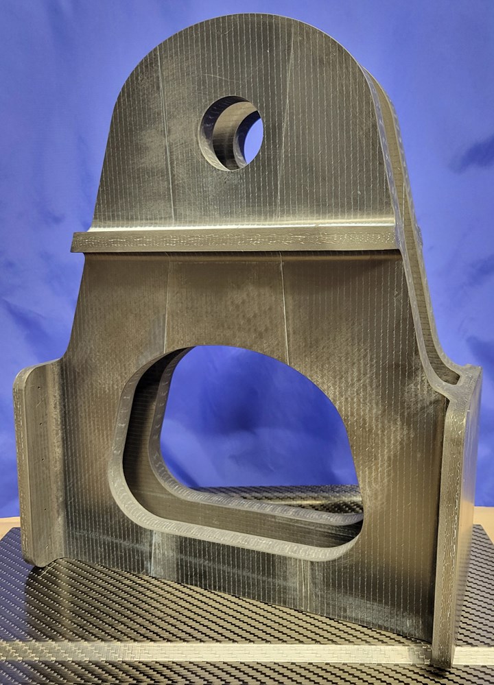
All of this is manifest in a variety of collaborative R&T projects, mainly in aerospace and defense. These include 3D weaving work on hypersonics applications, work with Airbus on the Wing of Tomorrow program, and work with CFM on its RISE (Revolutionary Innovation for Sustainable Engines) program, which aims to develop an open-rotor aircraft engine concept. We also caught sight, on the tour, of a complex vertical tailplane (VTP) fitting that AEC developed to TRL 3-4 for an unnamed customer (Fig. 8).
Looking ahead
Like every business throughout the world, AEC was not immune to the effects of the COVID pandemic, but Greg Harwell, president of AEC, says the company used the pandemic-induced pause to conduct a robust internal evaluation of its strategy and direction. “We re-invented ourselves,” he says.
This reevaluation helped AEC steer more of its efforts toward defense applications such that there is now a nearly equal split between that market and commercial aerospace. It also helped the company see the opportunities in non-weaving technologies, such as automated tape laying (ATL), automated fiber placement (AFP), braiding, filament winding and even hand layup.
And, like the rest of the aerospace supply chain, AEC is waiting for Boeing or Airbus to announce a new commercial aircraft platform. This has forced AEC (and others) into a two-pronged growth strategy — position itself to serve Boeing and Airbus with high-quality, cost-effective composites manufacturing when the next platform is announced, and leverage current technology strengths into new business.
Dill says AEC is in a strong growth position given the efficiencies and technologies it has built around the LEAP program. “With limited new platforms on the horizon, AEC performance has allowed us to play in the takeaway space, helping key customers remove problem suppliers effectively.”
Figure 8. Albany is eager to leverage its expertise in 3D weaving and RTM into other aerospace and defense opportunities that would benefit from the industrialization, automation and process control the company has developed for the LEAP structures. One example is this vertical tailplane fitting demonstrator fabricated for an unnamed customer.
One new award that AEC picked up recently is the Aft Transition Assembly section for the Lockheed Martin Sikorsky CH-53K King Stallion heavy-lift helicopter. AEC will build a new 100,000-square-foot facility to fabricate 150 composite details for the application.
The company is also establishing a development engineering program that will focus on applied technology and process development from design and structural analysis through qualification and low-rate production. Within AEC the capabilities include hand layup, braiding, filament winding, compression molding, infusion, 3D printing, RTM, autoclaves and CNC processes.
AEC is also pursuing innovation in design expertise to support a wide range aerostructures applications. To that end, and specifically focused on 3D woven composites, the company has developed design software, called 3D Composite Studio, that can be integrated with off-the-shelf CAD systems to add weaving programming capability. This software can also be used to conduct performance and process modeling to evaluate fibers in three dimensions, as well as virtual testing and simulation.
What does all of this mean for AEC? Harwell says the company is targeting to become 50% of parent company Albany International’s $1.2 billion projected revenue by 2026, with growth fueled entirely organically. What about inorganic growth? Harwell says AEC is always on the lookout for opportunities to add expertise and capability, but it must be highly targeted. For now, he likes the niche AEC has carved, focusing on technology, process control, industrialization and efficiency.
“That’s what’s unique about us,” Harwell says. “It’s really the combination of technology and operational excellence that drive the results you see at AEC. And the metrics that we are able to derive from that consistent quality and reliability has become a significant advantage for us.”
The ultimate enabler, as exemplified by the Rochester facility, is volume, which has become a game-changer for the company. Harwell says, “The critical evolution of managing volume is the ability to industrialize these opportunities and continue to be the industry benchmark.”
Related Content
Cryo-compressed hydrogen, the best solution for storage and refueling stations?
Cryomotive’s CRYOGAS solution claims the highest storage density, lowest refueling cost and widest operating range without H2 losses while using one-fifth the carbon fiber required in compressed gas tanks.
Read MoreNext-generation airship design enabled by modern composites
LTA Research’s proof-of-concept Pathfinder 1 modernizes a fully rigid airship design with a largely carbon fiber composite frame. R&D has already begun on higher volume, more automated manufacturing for the future.
Read MorePlant tour: Joby Aviation, Marina, Calif., U.S.
As the advanced air mobility market begins to take shape, market leader Joby Aviation works to industrialize composites manufacturing for its first-generation, composites-intensive, all-electric air taxi.
Read MoreManufacturing the MFFD thermoplastic composite fuselage
Demonstrator’s upper, lower shells and assembly prove materials and new processes for lighter, cheaper and more sustainable high-rate future aircraft.
Read MoreRead Next
Plant tour: Daher Shap’in TechCenter and composites production plant, Saint-Aignan-de-Grandlieu, France
Co-located R&D and production advance OOA thermosets, thermoplastics, welding, recycling and digital technologies for faster processing and certification of lighter, more sustainable composites.
Read MoreVIDEO: High-volume processing for fiberglass components
Cannon Ergos, a company specializing in high-ton presses and equipment for composites fabrication and plastics processing, displayed automotive and industrial components at CAMX 2024.
Read MoreDeveloping bonded composite repair for ships, offshore units
Bureau Veritas and industry partners issue guidelines and pave the way for certification via StrengthBond Offshore project.
Read More


