Composites testing at elevated temperature and moisture content
Dr. Donald F. Adams (Wyoming Test Fixtures Inc., Salt Lake City, Utah) notes the renewed interest in testing composites under hygrothermal conditions.
By the mid-1970s, it was generally recognized that the combined effects of elevated temperature and high moisture content reduced the stiffness and, especially, the strength of many polymer-matrix composites. Thus it was that in the second half of that decade — a very brief time period in the testing community — significant research was conducted to study these hygrothermal effects. In fact, Springer edited a two-volume compilation of much of this work, published in 19801 and 19842, respectively. Even today, this work stands as an excellent summary of the state of the art in this area.
One key conclusion of this extensive research is that moisture diffusion in polymers, and thus in polymer-matrix composites, does follow Fick’s Second Law, which for one-dimensional diffusion states that the rate of change of moisture content (m) with time (t) can be expressed as ∂m/∂t = D ∂2m/∂x2, where D is the coefficient of moisture diffusion. Thus, after D is measured for a particular composite, the moisture content anywhere within the structure can be calculated as a function of time, based on the initial (starting) condition of the material and the surrounding environment (boundary conditions). This information, along with measured coefficients of thermal and moisture expansion, permits the calculation of the dimensional changes of, and stress states within, the structure as a continuous function of time.
Because a composite material’s stiffness and strength tend to decrease as temperature and moisture content increase, these deformations and stresses can be significant in many applications. This includes the mechanical testing of composites. Temperature changes can be achieved in minutes, even in relatively thick composites. But desired moisture changes can require weeks or months. Because the coefficient of moisture diffusion, D, is a strong function of temperature, it is therefore desirable to expose the composite to moisture at a high temperature to reduce the conditioning time. But a high exposure temperature induces a high moisture gradient at the surface, and thus a high stress gradient, which can result in microcracking of the composite. Therefore, a tradeoff must be made.
Given the long conditioning times required prior to the actual testing, it has been customary to condition a large number of test coupons simultaneously in an environmental chamber at hygrothermal conditions. But the conditioning temperature typically is not the same as the subsequent mechanical testing temperature, because the latter is usually above the boiling temperature of water. Given that moisture desorption and moisture absorption are both governed by Fick’s Law, the concern is to prevent the specimen’s surface from drying out during mechanical testing. This can be done by maintaining the partial pressure of the water vapor in the test environment at the same level as that of the conditioning environment. For test temperatures higher than the conditioning temperature, this requires that testing be done in a pressure chamber.
All of this was well understood during the 1970s, and some minor attempts were made to conduct such testing. But because special equipment is required to maintain water vapor pressure and the test procedure is already time consuming, the whole issue eventually was ignored. A common alternative was to wrap a wet rag around the specimen and proceed. Of course, this did little to address the partial-pressure issue.
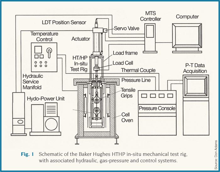
Today, after many years, a related issue is emerging. There are design applications where components, environmentally preconditioned or otherwise, are required to perform in hot and wet (and even worse) conditions. One example is the down-hole environment of oil-drilling operations. Temperatures of more than 200°C/400°F and pressures greater than 70 MPa/10 ksi combine with corrosive fluids to create a very hostile environment. When composite materials are evaluated for use in such environments, it is desirable to simulate those hostile conditions in the laboratory. For example, Baker Hughes Inc. (Houston, Texas) is developing mechanical test cells in which a candidate material can be exposed under the desired conditions for the desired length of time, right in the test fixture within the cell, and then be mechanically tested directly.3,4 Baker Hughes refers to this as its HTHP (high-temperature, high-pressure) mechanical test rig. Photographs of the actual apparatus are included in Yuan and Goodson4, but the schematic shown in Fig. 1 reveals the details clearly. Although the schematic shows tensile grips in place, the apparatus is equally capable of performing compression, shear and flexural loadings. For example, the chamber will accommodate a full-size Combined Loading Compression (CLC) test fixture (ASTM D6641), a full-size Iosipescu Shear test fixture (ASTM D5379) or a flexure fixture of comparable size.
As can be seen by the Yuan and Goodson publication dates (20073, 20084), the effort at Baker Hughes has been underway for some time. It remains very active, and additional facilities and capabilities are under development continually. Many very interesting results have been obtained to date. Some of these are presented in Yuan and Goodson and, undoubtedly, more will be published soon.
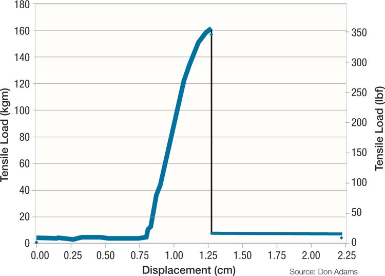
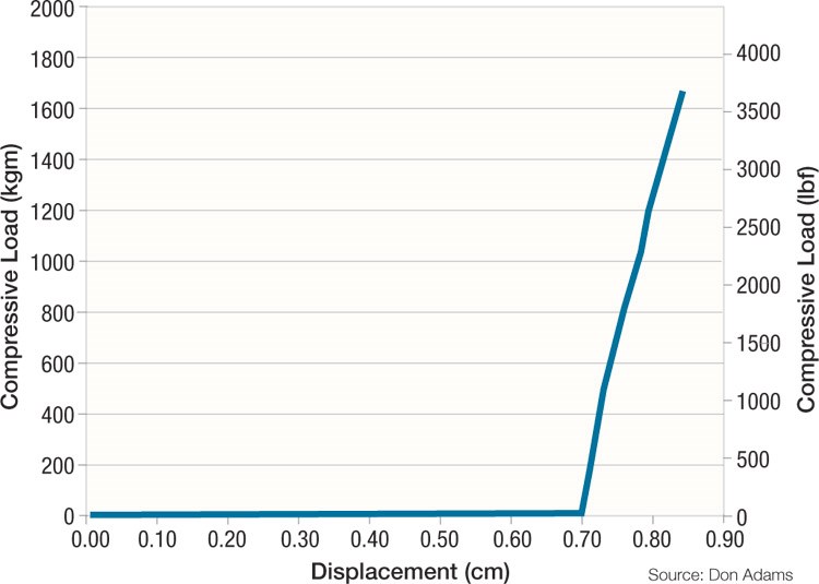
Samples from the published results are shown in Figs. 2 and 3. Fig. 2 shows an applied load vs. displacement plot for a tensile test of a neat epoxy resin. This specimen was exposed to a 3 percent NaCl brine solution at 149°C/300°F and 34.5 MPa/5,000 psi for 72 hours before it was tested at the same conditions. Several loads that could have a negative influence on the results — the weight of the grips suspended from the load cell, the chamber pressure pushing upward on the loading rod, and the friction in the seal around the loading rod — are compensated for when reducing the applied load vs. displacement data. Yuan and Goodson provide the details of data reduction along with additional experimental results. Fig. 3 is a similar plot for a compression test of a carbon fiber/epoxy composite. This specimen was exposed to a 3 percent NaCl brine solution at 204°C/400°F and 34.5 MPa/5,000 psi for 72 hours before it was tested at the same conditions.
Hopefully, this work by Baker Hughes Inc. will prompt others to renew general investigations of hygrothermal testing under controlled conditions of high temperature and high pressure.
Wyoming Test Fixtures Inc.
References:
1G.S. Springer, ed., Environmental Effects on Composite Materials, Vol. 1, Technomic Publishing Co. (Lancaster, Pa.) 1980.
2G.S. Springer, ed., Environmental Effects on Composite Materials, Vol. 2, Technomic Publishing Co. (Lancaster, Pa.) 1984.
3Y. Yuan and J. Goodson, “HT/HP Hot-Wet Thermomechanical Properties and HT/HP In-Situ Mechanical Test Method of High-Temperature Polymer Composites,” 52nd International SAMPE Symposium and Exhibition (Baltimore, Md.), June 2007.
4Y. Yuan and J. Goodson, “HTHP In-Situ Mechanical Test Rig and Test Method for High-Temperature Polymers and Composites,” Paper SPE 113516, SPE Europec/EAGE Annual Conference and Exhibition (Rome, Italy), June 2008.
Related Content
Plant tour: Arris Composites, Berkeley, Calif., U.S.
The creator of Additive Molding is leveraging automation and thermoplastics to provide high-volume, high-quality, sustainable composites manufacturing services.
Read MoreWatch: A practical view of sustainability in composites product development
Markus Beer of Forward Engineering addresses definitions of sustainability, how to approach sustainability goals, the role of life cycle analysis (LCA) and social, environmental and governmental driving forces. Watch his “CW Tech Days: Sustainability” presentation.
Read MoreASCEND program update: Designing next-gen, high-rate auto and aerospace composites
GKN Aerospace, McLaren Automotive and U.K.-based partners share goals and progress aiming at high-rate, Industry 4.0-enabled, sustainable materials and processes.
Read MoreCirculinQ: Glass fiber, recycled plastic turn paving into climate solutions
Durable, modular paving system from recycled composite filters, collects, infiltrates stormwater to reduce flooding and recharge local aquifers.
Read MoreRead Next
Developing bonded composite repair for ships, offshore units
Bureau Veritas and industry partners issue guidelines and pave the way for certification via StrengthBond Offshore project.
Read More“Structured air” TPS safeguards composite structures
Powered by an 85% air/15% pure polyimide aerogel, Blueshift’s novel material system protects structures during transient thermal events from -200°C to beyond 2400°C for rockets, battery boxes and more.
Read MoreAll-recycled, needle-punched nonwoven CFRP slashes carbon footprint of Formula 2 seat
Dallara and Tenowo collaborate to produce a race-ready Formula 2 seat using recycled carbon fiber, reducing CO2 emissions by 97.5% compared to virgin materials.
Read More


.jpg;maxWidth=300;quality=90)


