New Approaches To Cost-effective Tooling
New methods, materials and philosophies add up to tooling innovations.
As the composites industry has matured, so has the tooling industry that underpins composites fabrication. But toolmakers perennially find themselves on the horns of a dilemma — clients demand quality tools that deliver dimensionally accurate, high-quality parts, but balk at the costs and lead times necessary to produce them.
Especially in aerospace, new cost-saving tooling ideas are often stymied by the potential high cost of a part failure. Nevertheless, over the past five years, more cost-effective tooling innovations have proliferated, as vacuum and resin transfer molding (RTM) methods have been adapted for higher-performance applications. Traditional aerospace tooling is changing to take advantage of high-production-rate processing methods and new materials, while preserving part quality.
"We're not in the business of asking our customers to take big risks," says Rich Petrovich, president of North Coast Tool and Mold Corp. (NCTM, Cleveland, Ohio, U.S.A.). "Innovations are good, but they have to be proven."
That sentiment is echoed by all the companies interviewed for this article, from aerospace tooling suppliers to general industry moldmakers. "The bitterness of poor quality remains long after the sweetness of low price is forgotten," states Remco van den Berg, director of sales at Advanced Tooling Systems (ATS, Almelo, The Netherlands).
Raising the bar with liquid molding
RTM methods have multiplied over the past 15 years, as manufacturers have recognized the benefits of the process. A two-part, machined RTM mold delivers a smooth surface finish on both sides of the part and can produce complex, detailed, near-net shapes at a high rate with minimal post-production trimming. The fact that the resin is delivered under pressure with the mold halves clamped together (or held together in a press) means parts are consistent, repeatable, dimensionally stable and well-consolidated, with high fiber content (50 to 70 percent) and excellent void control (usually less than 0.2 percent). For high-performance parts made with higher-viscosity toughened resins, molds are usually heated (accomplished with heated oil galleys) and resin injection pressure is controlled with a meter/mix injection machine. Raw material costs are generally less than those for hand layup because dry preforms are used rather than traditional prepregs. Cycle time can range from two to three hours — shorter than typical autoclave cure cycles.
The relatively high cost of matched metal molds is usually justified only for high production runs, small parts or well-funded projects. But toolmakers are striving to overcome cost issues with innovations like modular tooling, removable inserts that can be configured for multiple parts, and alternative materials and approaches that reduce capital investment. For example, one tooling manufacturer, Dangar Engineering & Manufacturing Inc. (Newbury Park, Calif., U.S.A.), has developed a multipart automated RTM tooling concept with molds that slide on rails to eliminate mold handling. "We need a fast production method to compete against aluminum," says Dangar's president Dan Woods.
During the last decade, NCTM has introduced several RTM molding innovations to make the process more affordable and predictable for a variety of part sizes and shapes. A notable project was a modular RTM tool suite for customer GDATP — DeLand Operations (formerly Intellitec, DeLand, Fla., U.S.A.), used to produce carbon fiber/epoxy stiffener frames and bulkheads for the Apache AH-64A helicopter fuselage (see "Focus on Design," HPC January 2002, p. 40). The modular premise, borrowed from injection molding, involves a common mold base with interchangeable cavity inserts. The inserts allow production of different part shapes from the same mold, says GDATP's RTM program manager Dan Davenport. For the Apache, thirteen different frame components were produced from just two modular aluminum RTM molds, one of which was fabricated by NCTM. The insert tooling strategy cost 70 percent less than creating individual molds for each part, which enabled the development project to meet its non-recurring cost budget.
Directed resin injection and venting (DRIV) technology is another recent RTM tooling development from NCTM. In the DRIV tool, strategically placed mold inserts function as vents, allowing entrapped air to escape from the preform in a sequenced manner, which facilitates resin flow and wetout throughout the part cavity.
"Traditional liquid molding relies on uncontrolled resin flooding, with single point, edge-of-part venting," says DRIV inventor Petrovich. "Unfortunately, this type of approach tends to result in dry spots. Manufacturers increase injection pressure to improve wetout, but this can cause fabric movement and mold deflection." Further, says Petrovich, mold mass and clamping pressure are increased, all of which tend to limit the size and complexity of RTM parts. With the DRIV concept, pockets are machined into the inner mold surface; the pockets, either circular or oval-shaped depending on the part, contain small holes drilled through the mold thickness. Tiny vented inserts with serrated edges are then placed in the pockets as dictated by the part geometry. Air can vent through the insert into the pocket and out of the mold, but the serrations prevent resin flow. Or, says Petrovich, the serrations can be machined larger to allow telltale resin flow in a particular segment of the part. The inserts and pockets are designed so that no witness marks are created in the part.
"It's a belt-plus-suspenders approach that reduces risk," he explains. "The inserts help you ensure complete wetout — they can either be manually operated or controlled by computer in a defined sequence that facilitates the resin front." The DRIV RTM concept was used successfully by Lockheed Martin to mold a demonstration vertical stabilizer part for the Joint Strike Fighter (JSF) aircraft program. The part's venting layout was actually modeled by the University of Delaware's Center for Composite Materials, which demonstrated that the vent inserts improved the resin flow front geometry. With better wetout at lower injection pressure, less material was needed for the mold itself, which reduced overall tooling cost. Clamping pressure requirements also were lower.
"With DRIV, manufacturers can produce larger and more intricate parts, with higher fabric content and high viscosity resin," says Petrovich. The method can be applied to any type of liquid molding, including vacuum-assisted resin transfer molding (VARTM) and other infusion processes.
A big advantage with RTM is part consolidation — the ability to produce a complex component as a single molded composite part rather than an assembly of multiple parts typically required in metal. Radius Engineering Inc. (Salt Lake City, Utah, U.S.A.), involved with RTM tooling development since the mid-1980s, recently molded a prototype carbon composite wing flap that will replace a multipiece aluminum assembly on the Bombardier CRJ aircraft. Because the flap can be RTM'd as a single component, it is cost-competitive with the aluminum version, and the part's excellent surface accepts paint without the need for additional surface treatment.
The tool, made with vacuum-cast and anodized M1 aluminum mold plate, has a top and bottom half with outer molding line (OML) machined into each half. Anodized aluminum was selected for its surface hardness and its low specific heat and high conductivity, which permits faster heating than steel. It also has good vacuum integrity and can withstand RTM resin injection pressures. The mold includes an inner set of six aluminum mandrels fixtured together at their ends to control their positions relative to each other and to the OML. The 3.6m/11.7-ft long by 0.6m/2.3-ft wide part was designed so that braided sock preforms, supplied by A&P Technology Inc. (Cincinnati, Ohio, U.S.A.), could be fitted over each mandrel to form the flap's internal spar webs. Above and below the spars, tackified carbon fabric from HexcelHexcel Composites (Dublin, Calif., U.S.A.) forms the upper and lower skins. The approximately ten-fold difference in coefficient of thermal expansion (CTE) between the aluminum mold and mandrels and the carbon part is actually a design benefit — aluminum's much greater shrinkage makes it easy to remove the mandrels after cool down.
"The mandrels were designed so that closing the tool would force them into their final position and overcome the natural bulk of the inner braids," explains Emmanuel Pons, Radius Engineering's project manager. "Because of details shaped into the leading edge, the first mandrel was split to prevent any locking of the tooling."
Radius achieved good wetout using a single resin inlet at the center of the tool's leading edge and a single vacuum port at the center of the rear, injecting standard Hexcel RTM 6 epoxy resin at 100 psi. The tool featured a resin distribution "weir" that causes resin to flow along the tool's entire front edge, so that the part is impregnated across the broadest possible front, with the resin path proceeding from the leading edge to the trailing edge.
Radius manufactured the prototypes and the parts required for part certification; the actual production rate should be about 200 parts per year. The reduction in part count translated to cost savings that have offset the cost of the tooling development. The innovative tooling design was recognized as the award winner in the "Air Transport" category at the recent JEC Composites Show in Paris (April 1-3).
Alan Harper, managing director of Plastech Thermoset Tectonics Ltd. (Gunnislake, Cornwall, U.K.) envisions low-cost, low-risk automated RTM systems for general and industrial molders making 500 to 2,000 parts per year, without the capital investment in heavy matched metal tools and associated tool manipulation infrastructure.
"More economical molding methods are needed if the composite industry is to stay competitive with steel, aluminum and thermoformed plastic parts," says Harper. His firm has developed several innovations, including Multiple Insert Tooling (MIT) RTM, and has helped popularize a process known as Light RTM (LRTM), providing training, tool design and ancillary accessories and equipment.
The LRTM concept uses vacuum pressure to hold the two halves of a closed mold together, while injecting resin at very low pressure — essentially a hybrid of RTM and vacuum infusion processing. One mold half, usually the lower or female half, is relatively rigid, while the matching counter mold half is thin and relatively flexible. Typically a manufacturer can use his existing open mold if it has a suitable edge flange for sealing and resin injection; the matching counter can be readily fabricated on the lower mold. Advantages of LRTM include its simplicity and very low cost, ability to produce parts with gel coated surfaces on both sides, and the potential for producing four or five times as many parts per day as open molding. LRTM part tolerances are tighter and part-to-part consistency is greater than open-molded parts, but LRTM does not achieve levels associated with traditional RTM. Fiber volumes also are less, on the order of 18 to 20 percent.
Resin is injected at a pressure of 1 to 2 psi. Harper says the process works on the principle of peripheral injection, in which the resin is introduced around the periphery of the mold, between the edge of the part reinforcement and the inner pressure gasket, rather than at a single central injection inlet. Harper stresses that pressure control is critical, and that resin flow must be carefully controlled with a meter/mix machine and a pressure sensing and control device, such as Plastech's cost-effective Mould Pressure Guard (MPG) sensor or updated PV Sensor system, which allow precise machine pressure control in the millibar range.
"We've proven that with peripheral injection, you can inject resin four times faster than with a single inlet," he states. "But, pressure is the killer — if you over pressurize, you will simply warp the lighter, upper counter mold and end up with a too-thick component, which can exotherm and wreck the tooling."
MIT tooling, an RTM variation introduced about five years ago by Harper, incorporates multiple, identical, low-cost mold faces or skins, that can be quickly cycled in and out of the RTM mold press to increase productivity. While one skin is being injected and cured in the mold, others can be gel coated and loaded for the next cycle. Approximately 4 mm to 6 mm/0.158 inch to 0.25 inch thick, the skins can be composite, electroformed nickel, ceramic, elastomer or whatever material best suits the design. The system includes a heated hard tool base (which Harper calls a bolster), a matching upper counter mold, an offline "holding" bolster to support the MIT skins during demolding, and associated hardware.
"The production cycle is nearly three times faster with MIT than with a single mold, leading to a much quicker capital investment payback period, and obviously much less expense than multiple sets of RTM tools," explains Harper. Hot molds often play havoc with gel coat, but the fact that a cool MIT insert can be gel coated offline and placed in the heated bolster means the mold base can maintain its temperature, eliminating cooling time delays. The MIT process has been used successfully on fairly large — up to 23m2/240 ft2 — general molding parts using vacuum lifting frames to facilitate lifting the skins.
Some aerospace part allowables, however, simply cannot be met with LRTM or MIT, and more traditional tooling is sometimes the best answer. Plastech also has designed, built and supplied highly accurate composite RTM tools with steel backup structure for projects like the ASRAAM missile manufactured for the U.K. Ministry of Defence by MBDA UK Ltd. (formerly Matra BAE Dynamics), as well as matched metal RTM molds for other high-rate production parts.
Not-so-traditional tooling, too
For many applications, two-part RTM molds for liquid molding aren't the solution because of part size, materials or performance requirements. Tooling for complex aerospace parts has always required precision design and careful material selection because of technical issues, such as durability, CTE mismatch and tool movement during cure), that are beyond the obvious hurdles of cost and lead time. The standard approach has always been the "model-to-mold" route, starting with a certified master, often an intermediate "splash" or reverse mold, then the actual production mold and rate tools — all requiring a lot of time, materials and floor space. But toolmakers are pushing ahead to innovate in this arena, as well, with digital master patterns, new and more affordable materials, software changes and paradigm shifts in relationships with customers.
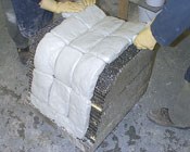
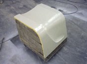
HPC's January/February 2001 issue (p. 20), reported that epoxy-based modeling pastes were being used not only for models, but inexpensive tools, as well. One example was The Boeing Co.'s (Chicago, Ill., U.S.A.) low-cost tooling for composites (LCTC) system. LCTC employs Vantico's (East Lansing, Mich., U.S.A.) Ren RP4040 syntactic epoxy tooling paste patties, which are pressed into a machined aluminum honeycomb substructure, and then cured and machined to final contour. Formglas (Toronto, Ontario, Canada) has since perfected the concept, proving that LCTC molds can be quickly fabricated directly from CAD data and autoclave cured for multiple part runs, with significantly lower lead times and cost. "It's the perfect tool for rapid prototyping of new structures or short-run operations," says Formglas technician Steven Burke.
The Ren RP4040 material has a CTE roughly equivalent to aluminum with thermal transfer rates comparable to carbon/epoxy prepreg tooling, in contrast to some other products like tooling boards. In addition, even after cure, it can be rebonded and remachined, to easily accommodate design changes or mold repair. A sealant compatible with the epoxy resin system used in the part is required to ensure vacuum integrity. Burke says the LCTC system can save as much as 70 percent in overall mold material and fabrication time, compared to traditional methods.
Long an advocate of cost-effective, low-hassle composite tooling, John Janicki, president of Janicki Industries (Sedro Woolley, Wash., U.S.A.), points out that, particularly for prototyping, the requirements of the tool (temperature performance, accuracy) must be reduced to keep tooling costs in line. "Our customers who are bidding on major programs like the Joint Strike Fighter are interested in new tooling technology, but in the end, most go for the tried and true, which often ends up being metallic tooling like Invar," states Janicki. "They all recognize the problems with Invar — like the cost, the lead times, the thermal mass, and the requirements for support infrastructure to move the tools around. One of the beauties of composite tooling is that it can accommodate any part shape — it opens up new opportunities for designers."
Janicki is trying to perfect a composite tooling system fabricated by resin infusing multiple plies of dry carbon fiber tooling fabric on a pattern to create a solid laminate approximately 19-mm/0.75-inch thick. A backup structure is attached and the entire assembly is postcured at 177°C/350°F. During the postcure, the tool moves due to resin shrinkage and "spring" — a change in the curvature of a thick laminate placed on a contour or radius. Rather than attempt to constrain the movement, the company machines the cured face to final tolerance. By using infusion to create the tool, air is forced out, resulting in less tool porosity and, therefore, a better surface finish. Janicki reports that while still under development, the method is rapid and cost-effective, and will provide aerospace-grade tools that are lighter than metallic tools, with faster thermal transfer rates and the same CTE as the parts currently being produced.
A recent challenge was the tool set for manufacturer North American Bus Industries Inc. (NABI, Woodland Hills, Calif., U.S.A.), which fabricates a 45-ft long, two-axle, low-floor monocoque bus structure with no separate metal chassis. Axles and suspension components attach directly to the CompoBus composite body. To get the necessary stiffness, the bus body had to be made almost entirely as a one-piece construction. Janicki produced a six-piece carbon fiber/epoxy composite tool that bolts together for layup and resin infusion, but disassembles for storage.
Janicki Industries also produced the composite tools used by AAR Composites (Clearwater, Fla., U.S.A.) to make the bodies for the Las Vegas rapid transit monorail system, in Nevada. The E-glass/epoxy composite tools with steel backup structures incorporated details like window and door cutouts, which allowed net layups without the need for postcure cutting and finishing.
Advanced Composites Group (ACG, Tulsa, Okla., U.S.A. and Heanor, Derbyshire, U.K.) points to its new ZPREG prepreg material as a means of making composite tooling more cost-effective. ZPREG, originally developed for making parts, consists of two layers of reinforcement enclosing the resin. Rather than a continuous layer, the resin is applied in approximately 12.5 mm/0.5-inch wide strips, with dry strips between. But, says ACG's aerospace sector manager Chris Ridgard, it can be used to make high-temperature composite tooling with an excellent surface finish without an autoclave. The company recently completed a 40m/130-ft long wind turbine blade tool in carbon fiber/epoxy ZPREG.
"Obviously, when you're making a 40m long part, autoclave cure isn't an option," says Ridgard. "With the ZPREG material, during cure, the dry areas between the resin strips provide escape paths for the air, which results in very low porosity and, consequently, much better surface finish."
The alternating dry and resin-impregnated strips means that 50 percent of the ZPREG material is dry, which gives it excellent drape and formability for layup. The resin is allowed to bleed through on one side of the prepreg, which gives it a slight tack. The ZPREG resin system has a broad processing window, ranging from 65°C/150°F to 150°C/302°F under a vacuum bag, but can produce tools capable of making parts that cure at 177°C/350°F.
Even for suppliers of more traditional metallic tooling, cost-effectiveness sometimes can be secured through changes in customer relationships, says van den Berg of ATS. "How can we reduce tooling costs? Get the tooling supplier into the process early on," he states. "We and other tooling houses have invested in engineering expertise, including CATIA5. We can do tooling design more cost-effectively than the OEMs."
Van den Berg points to the automotive industry as a model for what is starting to occur in aerospace and other industries. Typically the OEM shifts responsibility for supplying parts to the first-tier suppliers. For example, Mercedes designs a "marketing model" — a new convertible, for example — as a 3-D surface, and leaves the details of how the various parts will be tooled and assembled up to the suppliers. In order to meet the hard deadline for producing parts, the supplier and tool designer must work in concert, in a process van den Berg feels is truly "concurrent engineering."
"By working together with the part designers, you can develop a tool that can be modified later if changes are needed, which saves tremendous cost. Second, once the tool and part size are defined, the toolmaker can buy the tooling materials ahead of time, essentially sharing some of the cost risk with the customer, so that as soon as the CAD data is released, we can start milling," he explains.
ATS recently completed a tool set for Airbus Industrie that includes 64 tools for the A380 wing spoilers. The set includes 32 upper and lower skin layup tools in tooling steel, with 16 associated assembly jigs. Van den Berg reports that ATS is experimenting with new adjustable tools with thin face sheets made with Invar plate stock.
UCAR Composites Inc. (Irvine, Calif., U.S.A.) is another traditional aerospace tooling supplier that has streamlined its operation and reduced tooling lead times and costs with an innovative software approach. The company uses an integrated software management tool called VISUAL Enterprise from Lilly Software Assoc. Inc. (Hampton, N.H., U.S.A.) that combines manufacturing and quality functions for substantially reduced overhead expenses. The program tracks and prioritizes each tooling projection, estimated delivery times and production schedules, as well as quality issues for ISO 9000 compliance.
"The implementation of VISUAL Manufacturing helped get our scheduling and job costing under control," says UCAR's Bill Kansky, vice president of finance. "It has also helped meet our customers' demanding specifications and increased on-time deliveries to 98 percent."
An integrated software approach has also helped Apex Machine Tool Co. (Farmington, Conn., U.S.A.) reduce tooling development costs. The company employs Unigraphics Solutions from EDS (Maryland Heights, Mo., U.S.A.), a system that allows Apex to design, draft and machine an entire tooling project for true concurrent engineering. For a recent project, a customer's composite propeller design — also developed using Unigraphics — was readily downloaded into Apex's system, and engineers from both companies were able to collaborate on mold design throughout the process, for an on-time tool delivery and reduced cost. Apex has used its design expertise to develop unique break-apart mandrels for more efficient tooling designs, says Apex's composite designer Rich Walton.
More innovation coming
And we haven't even begun to touch on the truly different tooling approaches available, such as soluble tooling from Advanced Ceramics Research Inc. (Tucson, Ariz., U.S.A.); a reusable ceramic material that changes from a liquid to a solid state to quickly form a tool, developed by 2Phase Technologies Inc. (Dayton, Nev., U.S.A.); Roctool SA (Le Bourget du Lac, France) rapid resistive heating and inductive heating molding concepts; a foamed carbon material from Touchstone Research Laboratory Ltd. (Triadelphia, W. Va., U.S.A.); and a new composite tooling concept soon to be introduced by Scion Industries LLC (Ft. Collins, Colo., U.S.A.).
Given the countless possibilities for the design and fabrication of composite parts, the industry is counting on new innovations in the tooling to realize those parts. "People are looking for alternatives to aluminum, steel and titanium materials, particularly in the aerostructures industry, where the properties of composites bring so many advantages," says van den Berg. "The tooling industry will benefit from that."
Related Content
VIDEO: One-Piece, OOA Infusion for Aerospace Composites
Tier-1 aerostructures manufacturer Spirit AeroSystems developed an out-of-autoclave (OOA), one-shot resin infusion process to reduce weight, labor and fasteners for a multi-spar aircraft torque box.
Read MorePlataine unveils AI-based autoclave scheduling optimization tool
The Autoclave Scheduler is designed to increase autoclave throughput, save operational costs and energy, and contribute to sustainable composite manufacturing.
Read MorePlant tour: Airbus, Illescas, Spain
Airbus’ Illescas facility, featuring highly automated composites processes for the A350 lower wing cover and one-piece Section 19 fuselage barrels, works toward production ramp-ups and next-generation aircraft.
Read MoreBusch expands autoclave solutions
Busch announces its ability to address all autoclave, oven and associated composites manufacturing requirements following the acquisition of Vacuum Furnace Engineering.
Read MoreRead Next
Developing bonded composite repair for ships, offshore units
Bureau Veritas and industry partners issue guidelines and pave the way for certification via StrengthBond Offshore project.
Read MoreAll-recycled, needle-punched nonwoven CFRP slashes carbon footprint of Formula 2 seat
Dallara and Tenowo collaborate to produce a race-ready Formula 2 seat using recycled carbon fiber, reducing CO2 emissions by 97.5% compared to virgin materials.
Read MoreVIDEO: High-volume processing for fiberglass components
Cannon Ergos, a company specializing in high-ton presses and equipment for composites fabrication and plastics processing, displayed automotive and industrial components at CAMX 2024.
Read More




.jpg;maxWidth=300;quality=90)
