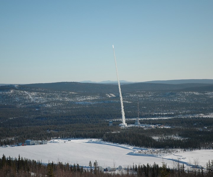
Moment of launch. The 23rd REXUS rocket takes flight on March 4, 2019, at the Esrange Space Center in Sweden. Source | DLR (German Aerospace Center)
On the frigid morning of March 4, 2019, at the Swedish Esrange Space Center north of the Arctic Circle, Ralf Engelhardt, research associate at the Chair of Carbon Composites at the Technical University of Munich (TUM), was waiting for a rocket to launch. This rocket, part of the REXUS program (Rocket Experiments for University Students), jointly managed by the German, Swedish and European space agencies, contained a carbon fiber-reinforced plastic (CFRP) module that Engelhardt and his team had spent more than three years designing, manufacturing and testing. As far as they knew, it would also be the first such rocket module manufactured by in-situ consolidation. They also knew that the module, which was 40% lighter than the aluminum modules typically used in these rockets, had passed a battery of coupon-level, sub-component level and full-scale tests. Nevertheless, Engelhardt would have to admit, in retrospect, “the launch was a challenge for my heart.” When the countdown began, the only way to be sure about the outcome was to sit back and watch.
In January — two months before launch — CW wrote about TUM’s CFRP rocket module experiment and the innovative manufacturing process behind it, which can be read here. Post-launch, CW was able to learn about the module’s flight performance, hear TUM’s next plans for composite rocket structures and discuss future applications of in-situ consolidation.
Module design and production
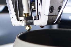
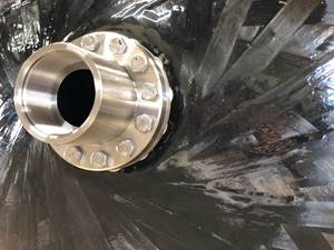
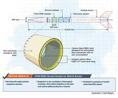
The module, located mid-fuselage between two other research modules, measures 356 millimeters in diameter and 300 millimeters long. It consists of a cylindrical shell structure joined to two load input rings on either end, which allow the module to be connected to adjoining modules. The load input rings are molded from Victrex plc (Lancashire, U.K.) polyetheretherketone (PEEK) 450CA30 long-fiber thermoplastic (LFT) granules. In the original design, they are press-molded, while the launched module includes centrifugally molded rings (see below for detail). The shell, made from Teijin (Tokyo, Japan) Tenax unidirectional carbon fiber/PEEK prepreg tape, is laid up and consolidated to the rings in-situ by thermoplastic automated fiber placement (TP-AFP). A robot arm (AFPT GmbH, Doerth, Germany) lays down the tape and heats it with a laser, consolidating the shell to the rings.
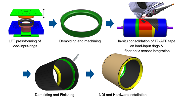
Fabrication process for the module. The module is created by in-situ consolidation of the rings and shell. This particular illustration includes the press-forming of the rings. Source | Technical University of Munich
The launch
On the morning of March 4, the good news was that the module survived the launch and several important measurements were recorded. As is typical with the REXUS program, maximum acceleration (at the moment of launch) was 20G and top speed was 1,200 meters per second. The flight reached a maximum height of 75,422 meters. The team additionally recovered flight temperature data from the fiber optic sensors (FOS) imbedded in the module’s shell (see previous story for detail). The maximum temperature readings for the inner and outer sensors, respectively, were 125.69°F (52.05°C) and 140.576°F (60.32°C).
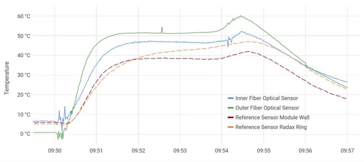
In-flight temperature data from the TUM’s module. This chart illustrates one-measurement-per-second live downlink data from the module’s fiber-optic temperature sensors. Source | Technical University of Munich
While these sensors were included to measure temperature, by recording data 10,000 times per second, they were also able to gather some vibration data as well. During flight, when the manacle ring that separates the payload from the motor opened, and when a student-developed project ejected three free-falling units from under the nose cone, several disturbances were caused in the high-frequency temperature recordings. These disturbances revealed vibrations and could also be filtered out to segregate thermal data from vibration data. Being able to gather multiple data types in this way minimized the number of sensors to be imbedded in the shell structure, which in turn preserved the integrity of the structure.
Unfortunately, there was also a complication with the test flight: a hard landing. Engelhardt says the parachute had a “non-nominal fill,” and as a result the rocket had an unplanned ground impact at 58 meters per second. Based on visual inspection, TUM’s module appears to have retained its structural integrity, and for Engelhardt, that is a win in its own right. The team is awaiting a post-launch CT scan, which will be performed by the German Aerospace Center (DLR) in Stuttgart and provide the final assessment of how well the module performed during the impact.
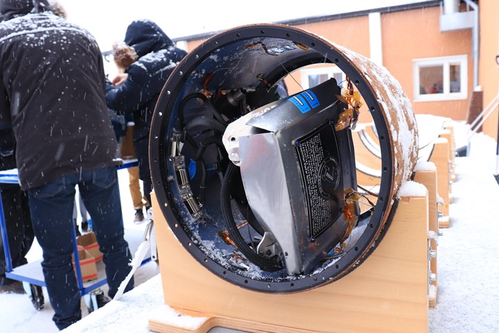
The module post-landing. While much of the internal sensing apparatus was dislodged, the module itself appeared to have survived the hard landing with little to no damage. Source | Technical University of Munich
Because they have CT scans from before the launch, DLR and TUM expect to jointly publish a comparison of the before and after scans. Engelhardt expects the CT scan results will be most interesting because of the hard landing, and he suspects that if the module did suffer delamination, the hard landing will be to blame for that: “Based on qualification [tests], we were sure it withstands loads during flight. This is something we proved. If we see there are delaminations [in the scans], we cannot prove it’s not coming from the flight, but everything we know lets us assume it is not coming from the flight.”
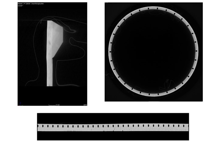
CT scans of rocket module. Top left: a cross-section scan of the upper interface between the load input ring (right) and cylindrical shell (left). The interface between shell and rings was revealed as a crucial section in Finite Element Method (FEM) analysis and was consequently scanned multiple times. This scan reveals an interface with “no noticeable problems,” according to Engelhardt, who added that “the TP-AFP laminate shows some dark spots, presumably being resin-rich areas coming from gaps between the tapes.” Top right: top-down CT scan of one of the module’s load input rings. Bottom: side-on CT scan of one of the module’s load input rings. Source | Technical University of Munich
What’s next?
With a mostly successful launch to its credit, TUM is pursuing more rocket and aerospace work. The team would like to launch a similar REXUS module without the cork insulation layer included in the March launch, primarily because the thermal loads recorded during the test were not as high as expected. Ideally, the team would also use a lower-performance material than the PEEK used in the March launch structure. However, that would entail an expensive and time-consuming requalification process, which would make material changes difficult.
Engelhardt would also like to manufacture the module’s load input rings with an in-house press molding process, as the team envisioned originally. Creating the press-molded rings would also enable the team to experiment with a recycling process. The recycling vision is to use waste carbon fiber fabric from the TP-AFP process used to fabricate the shell as feedstock for the next module’s rings. The rings used in the launched module were centrifugally molded by Elekem Ltd. (Lancashire, U.K).
If the team had more freedom and resources, they might consider even more ambitious modifications to the module. For instance, it might be possible to form a hatch in the module’s side by laying down a thickened frame of tape around the opening. Such a hatch is useful in missions where a probe or other object must be deployed from within the fuselage. Or, they could attempt to alternate the shell laminate’s thickness as a stiffening alternative to stringers.
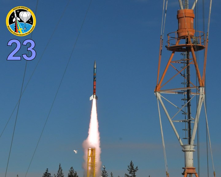
The module in flight. The TUM module is just visible as a brown segment between blue segments in the upper half. The brown is the cork insulation surrounding the module. Source | Thomas Schleuss, DLR (German Aerospace Center)
In-situ joints
The in-situ consolidation used to join the module’s shell and ring could have varied applications. TUM has incorporated the technique in some of its other projects, such as INSCAPE, in which a curved shell was in-situ consolidated onto stringers using TP-AFP. Engelhardt sees other uses as well: “Whenever you want to combine complex parts with a monolithic structure — brackets, hinges, or clips — if you want to combine something like this with a shell structure, then this process of combination can make sense.” He also envisions using this process to apply carbon fiber tapes to metal surfaces, resulting in hybrid material structures.
In-situ consolidation as practiced with the REXUS module presents multiple benefits. It shortens the process chain by combining part manufacturing and consolidation into a single step, eliminating costs and time delays along the way. This process may also be able to create further weight savings by eliminating fasteners. Such benefits may make it an appealing choice for future aerospace and rocketry research. Engelhardt points out that this technology could be an asset to the EU Clean Sky program, which aims to reduce aviation’s carbon dioxide emissions, in part through weight savings.
The REXUS rocket has certainly demonstrated the appeal of the method, along with the weight-saving benefits. Further scans are on the way to test the module and more innovations are sure to follow, but the future of composite materials in rocket flight has already taken a significant step forward.
Related Content
PEEK vs. PEKK vs. PAEK and continuous compression molding
Suppliers of thermoplastics and carbon fiber chime in regarding PEEK vs. PEKK, and now PAEK, as well as in-situ consolidation — the supply chain for thermoplastic tape composites continues to evolve.
Read MorePlant tour: Joby Aviation, Marina, Calif., U.S.
As the advanced air mobility market begins to take shape, market leader Joby Aviation works to industrialize composites manufacturing for its first-generation, composites-intensive, all-electric air taxi.
Read MoreA new era for ceramic matrix composites
CMC is expanding, with new fiber production in Europe, faster processes and higher temperature materials enabling applications for industry, hypersonics and New Space.
Read MoreInfinite Composites: Type V tanks for space, hydrogen, automotive and more
After a decade of proving its linerless, weight-saving composite tanks with NASA and more than 30 aerospace companies, this CryoSphere pioneer is scaling for growth in commercial space and sustainable transportation on Earth.
Read MoreRead Next
CFRP module saves weight on rocket design
Taking advantage of carbon fiber/PEEK mechanical and thermal performance, the Technical University of Munich replaces an aluminum rocket module with a 40+% lighter composite alternative.
Read MorePlant tour: Daher Shap’in TechCenter and composites production plant, Saint-Aignan-de-Grandlieu, France
Co-located R&D and production advance OOA thermosets, thermoplastics, welding, recycling and digital technologies for faster processing and certification of lighter, more sustainable composites.
Read MoreAll-recycled, needle-punched nonwoven CFRP slashes carbon footprint of Formula 2 seat
Dallara and Tenowo collaborate to produce a race-ready Formula 2 seat using recycled carbon fiber, reducing CO2 emissions by 97.5% compared to virgin materials.
Read More



.jpg;maxWidth=300;quality=90)


