
The path toward certification by simulation, Part 3: Simulation governance
Simulation governance is reportedly a prerequisite for certification by simulation, basically enabling V&V and UQ. And yet, it is claimed that the design of most simulation tools used today makes this very difficult, if not impossible. What is this hurdle and how do we overcome it?


I started this series of blogs with reference to Dr. Byron Pipes’ strategy to reduce the time and cost for composite structures certification by increasing the use of simulation and virtual testing. As he described in his March 2014 HPC column, “Accelerating the certification process for aerospace composites”:
“The most direct approach to reducing the cost and time of product certification is to first certify the simulation tools themselves. Certified simulation tools could be used by engineers with the expectation that, within the bounds of the certification, no further verification or validation would be necessary. This would result in enormous savings because the contemporary approach involves verification and validation testing by each user before the simulations can be trusted.”
This may appear pretty radical: certifying the simulation tool vs. the individual structural and/or manufacturing simulation. However, Pipes isn’t alone.


Dr. Barna Szabo, a retired professor of mechanics from Washington University (St. Louis, Mo., USA), asserts, “The only way to achieve certification by simulation is by instituting simulation governance.” He defines simulation governance as the procedures to ensure the reliability of numerical-based simulation predictions with the goal to reduce uncertainty and errors, including:
-
Formulating rules for collecting, verifying and archiving the experimental data input into simulations;
-
Applying the principles and procedures for verification and validation (V&V, see Part 1) and uncertainty quantification (UQ, see Part 2);
-
Establishing protocols for the revision of simulation tools and models in light of new information from UQ and physical testing.
Szabo is principal author of two textbooks on finite element analysis (FEA) simulation and is co-founder and president of Engineering Software Research and Development (ESRD, St.Louis).
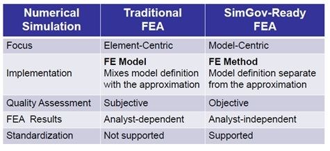
One of Szabo’s more intriguing assertions is that the conventional software tools in use today were not designed to support simulation governance. He says this is because the infrastructure of these products evolved long before the more recent maturation in simulation technology and formulation of the technical requirements for V&V. He explains, “The majority of the FEA programs have large finite element libraries that combine the mathematical model with its numerical approximation, making it impossible to identify and control the errors of idealization separately from the errors of approximation.” (See the figure below).
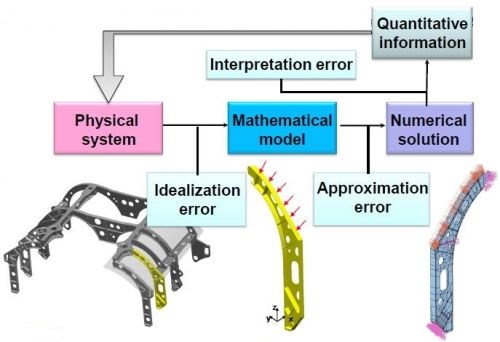
Dr. Barna Szabo asserts that simulation software must maintain independence between mathematical model formulation and numerical approximation. Only then is V&V possible. SOURCE: Engineering Software Research & Development, Inc. (ESRD)
In FEA, the analyst creates a mesh of discrete elements that allow approximation of the solution using standard approximating functions, typically polynomials. In conventional implementations the polynomial degree is at a low value (1 or 2) and the error can be reduced by decreasing the size of the largest element in the mesh (h). In the p-version, the mesh and the polynomial degree (p) of the elements can be controlled. This is especially important for composite materials where the aspect ratios of elements are typically large but local phenomena, such as boundary layer effects, require the use of small elements and high polynomial degrees.
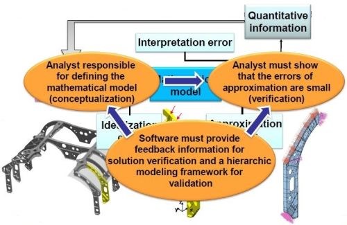
Szabo claims simulation tools developed in this way support hierarchic sequences of approximations and models. This hierarchic structure is important, as it allows comparing the data measured in validation experiments to the various assumptions incorporated in the model and ascertaining that the numerical error is not larger than the experimental error without changing the finite element mesh. According to Szabo, this also makes it feasible in professional practice to choose alternative mathematical models and investigate their effects on the predicted data, which is exactly what is required for V&V and UQ.
SOURCE: Engineering Software Research & Development, Inc. (ESRD)
Szabo gives ESRD’s StressCheck as an example of a simulation tool developed according to these principles. “It controls errors in numerical simulation by using the p-version of finite element modeling (p-FEM).” (Szabo is cited as pioneering the use of p-FEA during his tenure at Washington University). He continues, “P-version FEA increases simulation accuracy by checking for solution convergence through increasing the order of the approximating polynomials (p) in each element, not by decreasing the mesh size. Thus, it can reliably estimate the difference (Δ) between the data of interest corresponding to the exact solution of the mathematical problem (f) and their numerical approximation (fnum), and also provide means to ensure that the difference is within acceptable tolerances.”
StressCheck is used by a variety of organizations known for their leadership in composite structures:

“There are strong economic incentives for decreasing reliance on physical testing in engineering design and certification,” Szabo concludes, “but first we must be able to quantify the errors of idealization separately from the errors of approximation and provide evidence that they are sufficiently small.”


.jpg;maxWidth=300;quality=90;format=webp)


Read Next

Plant tour: Daher Shap’in TechCenter and composites production plant, Saint-Aignan-de-Grandlieu, France
Co-located R&D and production advance OOA thermosets, thermoplastics, welding, recycling and digital technologies for faster processing and certification of lighter, more sustainable composites.
Read More
“Structured air” TPS safeguards composite structures
Powered by an 85% air/15% pure polyimide aerogel, Blueshift’s novel material system protects structures during transient thermal events from -200°C to beyond 2400°C for rockets, battery boxes and more.
Read More
All-recycled, needle-punched nonwoven CFRP slashes carbon footprint of Formula 2 seat
Dallara and Tenowo collaborate to produce a race-ready Formula 2 seat using recycled carbon fiber, reducing CO2 emissions by 97.5% compared to virgin materials.
Read More