
3-D preforms: Fast, efficient blade-root manufacture
To expedite the blade root manufacturing process for wind turbine blade manufacturers, 3TEX Inc. (Cary, N.C.) has developed RapidRoot, a 3-D preform.

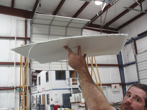
A RapidRoot 3-D preform, designed and assembled by 3TEX (Cary, N.C.). Source: 3TEX
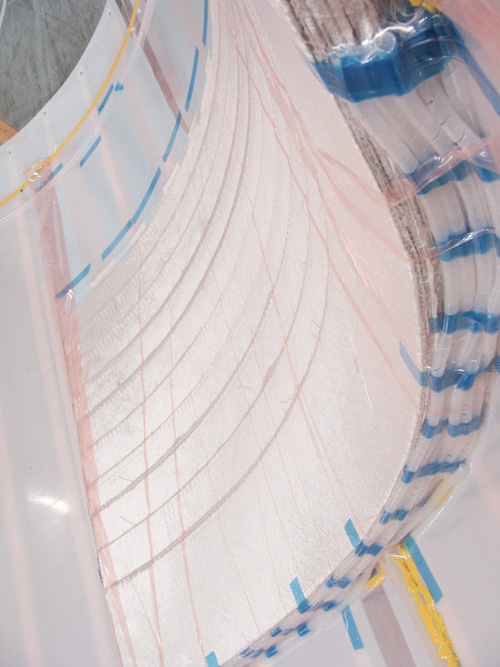
A root section layup, vacuum bagged and ready for infusion (note the resin distribution lines at the end of the laminate stack). Source: 3TEX
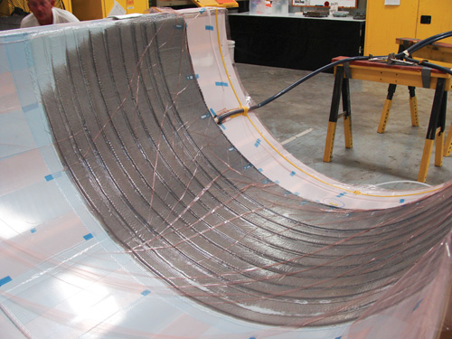
The resin front progresses evenly through the thick layup. Source: 3TEX


A wind turbine blade is basically a rotating wing, and as such, the consistency of its design and manufacture is critical to efficient wind energy generation. A single 40m/131-ft wind blade can weigh as much as 25,000 lb/11,340 kg. The forces exerted on the blade by the wind and gravity during rotation exert significant mechanical loads on the blade’s root section.
The root is the thick, round terminus of the blade that attaches to the hub of the turbine. The root not only maintains the connection between the blade and the hub, but it also bears much of the centrifugal load exerted by the blade as it rotates around its axis. Root sections are traditionally molded in halves and produced separately from the rest of the blade. After cure, the two halves are demolded and mated via bonding and then trimmed, sanded and attached to the blade to complete the structure.


From a composites perspective, the design of a 40m wind blade root section is notable for two reasons: It is relatively thick (up to 100 mm/4 inches) and relatively large (up to 2m/6.6 ft diameter); and it is also a tapered structure. Its thickest section is at the base of the root, and then tapered plies decrease the thickness of the root section along its length (about 1m/3.3 ft) until it matches the thickness of the base of the blade. The root section is typically infused under a vacuum bag and requires a consistency of strength, durability and quality that can be challenging in such a thick, large part.
To expedite the root manufacturing process, and to bring consistency of quality to the root section, 3TEX Inc. (Cary, N.C.) has developed RapidRoot, a 3-D preform of 8-mm/0.31-inch thick E-glass that replaces the 100+ individual plies in a conventional root layup. Delivered in rolls or provided flat, precurved or cut-to-spec, with a variety of fiber orientation options (e.g., 0°, 90° and ±45°), it also is provided in cut lengths, designed to provide the taper required.
Don Wigent, technical product manager at 3TEX, says fiber volume by weight with RapidRoot can be as high as 76 percent, and the thick, stiff nature of the fabric provides straight fiber lines in the finished part. Infusion of a root section with RapidRoot is done through one port at the base, or bolt end, of the root layup.
Wigent reports that the primary benefits conferred by the RapidRoot system are its ease of layup and the speed of infusion. The 3-D nature of the preforms — at weights of 5,400g/m2 or 10,500g/m2 — which are stiff but still somewhat flexible, makes them easy to place in a mold and slide into position without wrinkling or distorting the fabric. Further, the fabric’s architecture incorporates flow channels that optimize resin flow. A root layup reportedly can be infused in as little as 10 minutes with a 200-cps resin.
3TEX, working with North Carolina State University, has tested a variety of ply drop structures molded with the RapidRoot system. The woven taper design showed stress-at-delamination of 200 MPa. Square drops showed stress-at-delamination of 150 MPa. A woven taper with three thin knits at the tip showed stress at delamination of 210 MPa. A series of drops with 1,200g/m2 triax and with 900g/m2 at 0°/90° showed stress-at-delamination of 190 MPa. The data show that root sections made with the RapidRoot system can meet or exceed the strength and durability of conventional root fabrics/materials, says Wigent.


Related Content

Bladder-assisted compression molding derivative produces complex, autoclave-quality automotive parts
HP Composites’ AirPower technology enables high-rate CFRP roof production with 50% energy savings for the Maserati MC20.
Read More
COMPINNOV TP2 project promotes use of thermoplastics in aerospace
Completed in 2023, COMPINNOV TP2 explored thermoplastic composites, enhancing the understanding between prepregs and production methods to foster the potential for French aerospace innovation.
Read More
Plant tour: Albany Engineered Composites, Rochester, N.H., U.S.
Efficient, high-quality, well-controlled composites manufacturing at volume is the mantra for this 3D weaving specialist.
Read More
CompPair adds swift prepreg line to HealTech Standard product family
The HealTech Standard product family from CompPair has been expanded with the addition of CS02, a swift prepreg line.
Read MoreRead Next

Wind turbine blades: Big and getting bigger
Two decades of technical and market development has made this once marginal application a global giant and one of the world’s largest markets for composites.
Read More
Big Blades Cut Wind Energy Cost
Rapid growth rate of composite-intensive conversion systems drives market competition and innovation.
Read More
“Structured air” TPS safeguards composite structures
Powered by an 85% air/15% pure polyimide aerogel, Blueshift’s novel material system protects structures during transient thermal events from -200°C to beyond 2400°C for rockets, battery boxes and more.
Read More