Building a better tail boom
Out-of-autoclave carbon fiber/thermoplastic demonstrator is a 30 percent lighter drop-in replacement for an existing aluminum design.
Branches of the U.S. armed forces and their contractors continue to seek alternatives to autoclave cure in the manufacture of composite parts and assemblies used in military aerospace applications. The primary reason is that autoclaves involve high cost, both in terms of acquisition and operation. But secondarily, there are currently too few autoclaves available to new military programs because many of the autoclave-equipped composite fabricators that could serve them are already committed to existing aircraft programs, such as the Boeing 787 and the F-35 Lightning II Joint Strike Fighter. Further, the need for composites has never been greater as military engineers press on in their efforts to lightweight aircraft hardware.
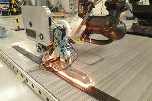
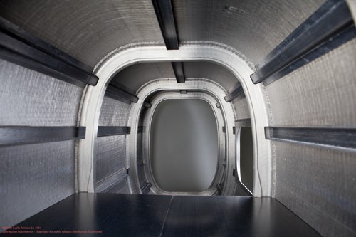
There are encouraging signs that alternatives will be found. A case in point is Automated Dynamics’ (AD, Schenectady, N.Y.) recently manufactured composite helicopter tail boom demonstrator. The part not only validates the ability of the company’s unique — and by definition, out of autoclave (OOA) — automated fiber placement (AFP) process to achieve both objectives. The tail boom is more than 30 percent lighter than comparable booms made of aluminum. But the benefit doesn’t end there. Helicopters are frequently designed with extra weight in the nose to properly place the craft’s center of gravity. Weight savings in the boom, then, pays dividends. For every 1 lb/0.45 kg of weight removed from the tail, engineers can remove up to 3 lb/1.36 kg of weight in the nose.
Tale of a tail boom
The composite tail boom project is an ongoing, multiphase U.S. Naval Air Systems Command (NAVAIR) program that was launched in 2007. The most recently completed phase had a threefold objective:
- Demonstrate the capability of AD’s fiber-placement process to manufacture a composite boom that simulates, to scale, the boom of a commercialized military helicopter.
- Fabricate a subscale part to demonstrate that the fuselage stiffeners are fully integrated and melt-bonded to the skin.
- Confirm the time and cost savings associated with simple, single-setup tooling.
The first phases comprised conceptual and design work, and material and process evaluation, and culminated with the manufacture of a complete tail boom demonstrator.
Taking cure out of the equation
The effort is especially notable because, while other programs have attempt to find faster and less-expensive ways to cure thermoset composites, the AD program has sidestepped the issue of cure altogether. The tail boom and its structural components were manufactured from a thermoplastic-based carbon fiber prepreg. Unlike an OOA thermoset-based prepreg, which, after layup or automated placement, must still be cured in an oven, the thermoplastic prepreg, an AS4/PEEK (polyethertherketone) unidirectional tape supplied by Cytec Industries (Woodland Park, N.J.), is consolidated on the fly via hot gas and heated rollers that melt and compress the laminate immediately after tape placement. When the consolidated laminate is cool, no additional processing is necessary. This alone saves much time and money.
The company claims the resulting laminate, in line with the previously listed project goals, is melt bonded at the molecular level, which lends the process to the production of net-shaped, integrated parts and structures free of fasteners and secondary adhesives. Further, the AS4/PEEK material is approximately 68 percent continuous carbon fiber by weight. As a result, the process achieves a fiber-volume fraction equal to that possible in autoclave processes.
Tail boom reevaluation
AD employs its thermoplastic-based fiber and tape placement technology to manufacture several parts for the gas and oil, fluid handling and aerospace industries. It also has built composite boom demonstration articles for four other helicopter platforms, most completed about 10 years before the current project. These demonstrators were used by customers to qualify materials, components and manufacturing processes to a variety of performance specifications. Since then, the cost of AFP has come down considerably — so much that the U.S. Navy and an as-yet unidentified helicopter manufacturer decided to reevaluate the technology as a possible stepping stone to commercial production of a composite tail boom.
“We’re running our fiber- and tape-placement production three to four times faster than when we built those early demonstration booms,” points out Chip Quinn, director of business development at AD, noting that the materials and processes also have accumulated 10 more years of qualification.
Company president Rob Langone adds, “Over the past decade, there has been significant maturation of both materials and process, which have yielded a cost and performance justification for their use.”
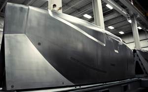
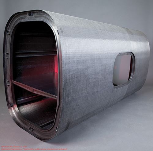
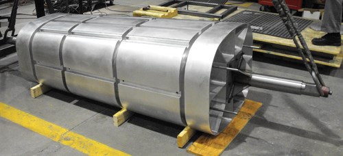
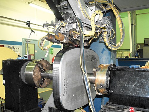
The subscale boom is roughly conical in shape, with forward cross-sectional dimensions of about 28 inches by 36 inches (710 mm by 914 mm), an aft cross section of 24.5 inches by 31.5 inches (622 mm by 80 mm), and a total length of 60 inches (1,524 mm). The part’s tubular shape required a “trapped-shape” tool design, assembled from segments, that could be dismantled and removed after the part was fabricated. Weber Manufacturing Technologies (Midland, Ontario, Canada) designed and built the tool’s five hollow interlinked sections, or inserts, each of which corresponds to one of the five compartments separated by four bulkheads within the boom (see Step 1 photo).
Weber used 5-axis CNC equipment to machine each section from aluminum billets. Tom Schmitz, business manager at Weber, says 2618 Al was selected for its toughness and dimensional stability during machining. One of the benefits afforded by the thermoplastic-based OOA AFP manufacturing process is that it permits the substitution of aluminum for a more costly alloy with a low coefficient of thermal expansion (CTE). A low-CTE steel alloy, such as Invar, would be required for tooling used to manufacture a part from a thermoset prepreg because adequate consolidation usually involves exposure to high temperatures in an autoclave cycle.
Schmitz reports that Weber has built dozens of trapped-shape tools for parts with undercuts, but rarely a tool with so many large segments for AFP manufacturing. The large dimensions of the boom, coupled with the requirement that the tool be attached to a spindle for fiber placement, presented a unique design challenge. “You have to find a way to keep everything rigid,” Schmitz says, “so when the tool is on its side and rotating on a spindle, gravity and the moment of inertia do not make the tool surface deflect.”
After finishing operations, each tool section was anodized (the oxide layer protects the tool from abrasion). The tool insert sections are held together by clamps attached to the mating surfaces within the inner diameter of the tool core. Each insert was designed to translate (collapse) when the clamps are removed so they could be pulled out of the finished part. Schmitz says one of the keys to the proper functioning of the tool was designing inserts with enough load-bearing capacity on the mating surface to ensure rigidity, yet not so much surface area that it would impede or prevent the insert from moving inward to clear the bulkheads.
“In a tool like this, you have to seek a balance of real estate, because you have to keep in mind not only that you have to make the tool rigid, but also that you have to remove the tool by hand after it is made,” Schmitz says.
Boom fabrication a multistep process
Prior to boom fabrication, and as part of the multiphase NAVAIR program, the materials and the AFP process were qualified to a number of specifications. One of the chief material specifications was short-beam strength. John Michasiow, program manager at AD, says ASTM D 2344, “Standard Test Method for Short-Beam Strength of Polymer Matrix Composite Materials and Their Laminates,” was used to evaluate the interlaminar shear strength of all AS4/PEEK materials. Each variation in material layup sequence and geometry that would be used in the construction of the composite tail boom had to meet the spec. Michasiow reports that Cytec’s AS4/PEEK was selected not only because its performance properties meet the required specifications but also because it is a readily available material and has an extensive history of testing with available published data.
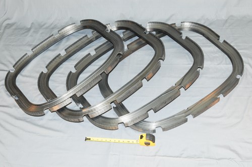
The tail boom features four hoop stiffeners (bulkheads) and 10 longitudinal stiffeners — six C-channel stiffeners and four hat stiffeners. The bulkheads and C-channel stiffeners were manufactured with AFP, and the hat stiffeners were hand layed. The laminate for each bulkhead was consolidated in situ by heated inert gas and heated rollers at the placement head; however, the laminates of both the C-channel stiffeners and hat stiffeners were consolidated via an autoclave cycle.
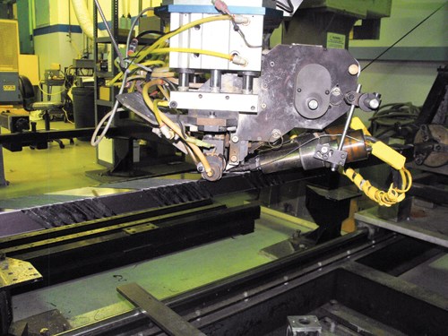
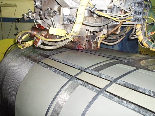
The 2-inch/50.8-mm wide AS4/PEEK prepreg tape was continuously placed around the circumference of the bulkhead portion of the tool to a thickness of approximately 2.5 inches/63.5 mm. Each tape layer is about 0.006-inch/0.152-mm thick, so the bulkhead comprises about 416 layers of tape. Each layer is consolidated in situ by rollers that are heated with gas torches to 975°F/524°C. The placement of 2-inch wide tape is twice as fast and more cost-effective than fabricating the bulkhead with adjacent layers of 1-inch/25.4-mm tape. Additionally, there were savings in energy cost because the greater width required only the addition of a third nitrogen hot-gas torch to the two that are used when a part is fabricated from 1-inch tape.
Because the boom skin would be bonded to the entire circumference of each bulkhead, the final bulkhead surface had to be held to a tight tolerance relative to the tool surface. Michasiow reports that fiber-placed parts are capable of achieving tolerances of about ±0.002 inch/±0.051 mm on the inner mold line (i.e., along a closed section of a part or cylinder). However, holding similar tolerances along the outer mold line with AFP often requires postprocess machining. The tolerance in this case is ±0.005 inch/±0.127 mm. After the completion of fiber placement, each bulkhead was CNC-machined on the tool to meet the specified tolerance (this also reduced weight).
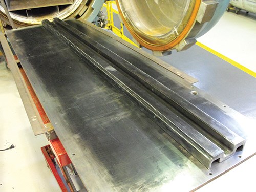
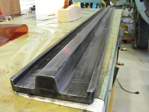
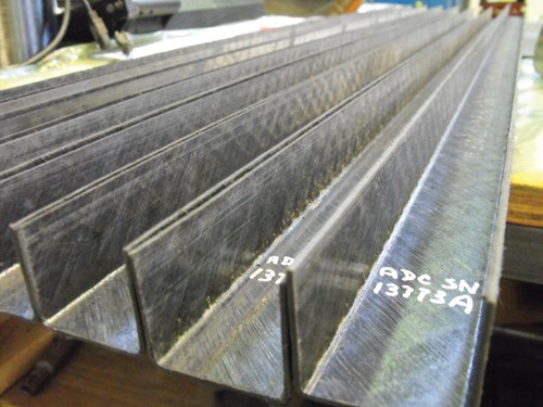
In general, the shape of a stiffener determines how it handles loads. A hat stiffener provides more load-distributing surface area than a C-channel stiffener (see step photos). For this project, the choice of type, size and location of stiffeners was driven partially by structural analysis, but it also was influenced by the availability of existing tooling, according to Michasiow.
To make each of the four hat stiffeners, operators hand layed 1-inch wide AS4/PEEK tape to a thickness of 0.066 inch/1.676 mm in a steel fixture. The architecture of the layup was quasi-isotropic. Prior to production, a 12-inch/305-mm long test piece was fabricated, placed in the autoclave under standard conditions for a thermoplastic and then consolidated. This confirmed that the tooling could produce a hat stiffener with flat, level flanges. After they cooled, the hat stiffeners were 3-inches wide at the base, 1 inch tall, 1 inch wide at the top and 0.070 inch thick (76.2-mm by 25.4 mm by 25.4 mm by 1.778 mm).
C-channel stiffeners were automatically fiber placed as box beams. Because the stiffeners were going to be consolidated in an autoclave cycle after layup, complete consolidation during AFP was not a concern, so the box beams were manufactured at an increased processing speed and a lower process temperature. The layup architecture was, again, quasi-isotropic. After the autoclave cycle, the box beams were cut in half laterally to create two C-channel stiffeners, each 1.75 inches wide, 1 inch tall and 0.070 inch thick (44.5 mm by 25.4 mm by 1.778 mm).
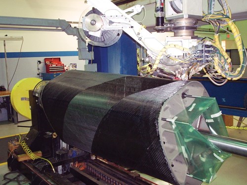
Then the bulkheads were inserted into the tool between the five sections. The hat and C-channel stiffeners were inserted into their respective grooves, and then the completed assembly was loaded into an AD fiber placement work cell for placement of the tail boom’s outer skin.
The architecture of the skin layup was determined by an analysis carried out by MR&D LLC (Raleigh, N.C.) earlier in the project. The skin comprises 12 plies in quasi-isotropic layup for a total thickness of 0.072 inch/1.829 mm. As the skin was placed, it was melt bonded to the stiffeners, bulkheads and window apertures, effectively joining the components in a single composite structure, without the need for fasteners or adhesives.
Boom process evolution
Using its AFP process, AD has produced a number of aerospace parts that are currently in commercial use. One of the most recent is a carbon/PEEK composite driveshaft 4.5 inches/114.3 mm in diameter by 24 inches/610 mm in length, which is a bolt-in replacement for a titanium drive used in a major military helicopter. The company also has fabricated other stiffened skin structures, including a fuselage tub, floor panels, horizontal stabilizer and fuselage frame/skin sections.
If and when an all-composite helicopter tail boom is approved by NAVAIR for use in active service on military helicopter platforms, the manufacturing methodology used to produce the demonstration boom will likely require tweaking. In particular, AD is investigating faster, more cost-effective ways of manufacturing the bulkheads and stiffeners. At the time the demonstrator tail boom was made, Michasiow reports, autoclaving the stiffeners was the best available option because alternative means for producing parts with the requisite structural properties had yet to be tested and qualified. Likewise, Michasiow adds, further testing might reveal that the bulkheads were overengineered. If that proves to be the case, less costly materials (e.g., chopped glass fiber) might suffice to meet the bulkhead structural requirements. In the case of both the stiffeners and the bulkheads, AD is evaluating substitutes for manufacturing by hand layup and fiber placement. Processes under consideration include compression molding and a continuous stamp-press manufacturing process.
These modifications, and AD’s ongoing efforts to further reduce costs, could yet pave the way for successful fielding of an all-composite helicopter tail boom manufactured by a process that is entirely autoclave-free.
Related Content
ATLAM combines composite tape laying, large-scale thermoplastic 3D printing in one printhead
CEAD, GKN Aerospace Deutschland and TU Munich enable additive manufacturing of large composite tools and parts with low CTE and high mechanical properties.
Read MoreNine factors to consider when designing composites cure tooling
Gary Bond discusses the common pitfalls and compromises when designing good cure tooling and their holistic significance for a robust composite production process.
Read MoreRocket Lab begins installation of large AFP machine for rocket production
The 99-ton AFP machine, custom-designed and built by Electroimpact, is claimed to be the largest of its kind, expecting to save around 150,000 manufacturing hours in the Neutron rocket’s production process.
Read MoreAirbus video highlights RACER compound helicopter first flight
Launched as part of a Clean Sky 2 program, a compound design — rotor, split fixed-wing, propulsive propellers — uses composites to cut fuel consumption and emissions by 20%.
Read MoreRead Next
VIDEO: High-volume processing for fiberglass components
Cannon Ergos, a company specializing in high-ton presses and equipment for composites fabrication and plastics processing, displayed automotive and industrial components at CAMX 2024.
Read MoreAll-recycled, needle-punched nonwoven CFRP slashes carbon footprint of Formula 2 seat
Dallara and Tenowo collaborate to produce a race-ready Formula 2 seat using recycled carbon fiber, reducing CO2 emissions by 97.5% compared to virgin materials.
Read More“Structured air” TPS safeguards composite structures
Powered by an 85% air/15% pure polyimide aerogel, Blueshift’s novel material system protects structures during transient thermal events from -200°C to beyond 2400°C for rockets, battery boxes and more.
Read More


.jpg;maxWidth=300;quality=90)


