Composite air brakes: Stopping the world’s fastest car
CFRP sandwich structures a key element of deceleration in the Bloodhound SSC rocket-powered racer’s two-run attempt at resetting the land speed record.
Design Results:
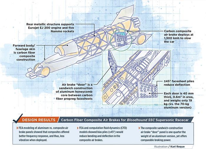
- FEA modeling of aluminum vs. composite air brake panels showed that composites offered better frequency response, and thus, less vibration when deployed.
- FEA and computation fluid dynamics (CFD) models showed bias plies (±45°) would reduce bending and deflection in the composite air brakes.
- The composite sandwich-construction air brake “door” panel is one quarter the weight of an aluminum version, yet offers comparable braking power.
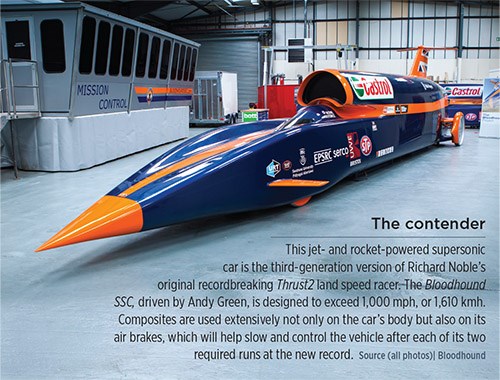
A tiny French Jeantaud Duc electric vehicle set the first wheeled-vehicle land speed record of 63 kmh, in 1898. One hundred years later, Richard Noble drove the Thrust SSC jet-powered vehicle to the first supersonic and still unbroken record of 1,227.985 kmh, in Black Rock Desert, in the US state of Nevada. Now, Noble and a team of engineers aim to smash his own record in pursuit of a much more ambitious goal: 1,610 kmh, the mythic land speed record milestone of 1,000 mph. The attempt will be made in 2016 at Hakskeen Pan, South Africa, in a third-generation supersonic jet-/rocket-powered vehicle, dubbed the Bloodhound SSC.
“This project represents most aspects of what would be seen in a major aerospace program,” says Tim Edwards, the engineer who oversaw a team within Atkins’ (Bristol, UK) aerospace business division, which was responsible for structural analysis of the vehicle’s composite elements as consultants to the Bloodhound engineering team. “We were engaged by Bloodhound because of our experience in the analysis of laminated composite structures — especially for aerospace applications.” Edwards’ team also helped interpret loads from the whole-vehicle finite element model and select analysis methods for specific components.
Although the car’s sole purpose is to achieve extreme speed, significant constraints dictated its design. Lightweight carbon composites could be used to create the slender yet highly curved aerodynamic forward body shell and engine intake, but heavier aluminum/titanium construction was required rearward to withstand the elevated rocket exhaust temperatures. Because the 7.5-MT, 13.5m-long car will be shipped to South Africa for the record run, the vehicle had to include a mid-length joint to permit disassembly for easier handling. Most important, rules require that two runs must be made in opposing directions (recorded speed is the average of the two) within one hour, so the car must be stopped, refueled and turned around very quickly. “Acceleration, deceleration and refueling time are critical, and no time can be wasted in slowing down,” Edwards points out, “So, in addition to powerful propulsion, braking is a key element.”
Slowing a rocket
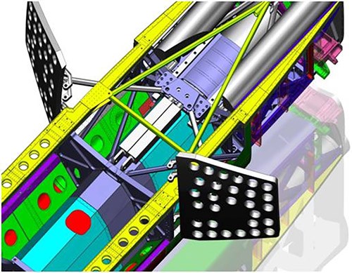
Braking won’t be easy: Powered by the same type Rolls-Royce EJ200 jet engine used in the EuroFighter Typhoon aircraft and five rocket engines from Nammo (a Jaguar 550-hp V8 engine will be used just to pump liquid rocket fuel!), the Bloodhound will cover the 1.6 km-long record segment in a mere 3.6 seconds. To stop it within the confines of the 19.3-km lake bed test track, Bloodhound’s engineers will rely on huge aerodynamic drag to slow the car to about 1,300 kmh. Then, two slaved, ram-actuated airbrakes, one on each side of the car, will open outward like doors from the craft’s body. Similar to aircraft speed brakes, they are designed to slow the car to 300 kmh, when wheel brakes will engage. Edwards explains that the positions of the airbrakes, their actuator arms and door hinges were dictated by the available space inside the vehicle (see drawing, top left), the lack of which meant that each door could be no larger in area than 0.6m2 and no more than 50 mm thick. “We were tasked to consider a door machined from a single piece of aluminum vs. a composite door,” says Edwards. Perforations in the doors will break up the airflow, but ensure that oscillatory loading on the rear suspension assembly, located immediately behind the airbrakes, will be minimized. “To avoid any possibility of the natural frequency of the doors coinciding with the frequency of vortex shedding effects from the car’s body,” he adds, “any material had to exhibit a minimum first natural frequency of at least 45 Hz.” Further, the design must withstand aerodynamic loading when deployed at speed, without excessive deflection or flapping. Given these parameters, a modeling and design effort was carried out to determine the best material choice. A finite element analysis (FEA) model of the air brake door was constructed — using HyperMesh and HyperWorks from Altair Engineering Inc. (Troy, MI, US) — by using the mid-plane surface from the air brake door CAD model and creating a 2D element mesh on that surface, explains Edwards. “Mid-plane models were also created in a similar way for each of the four hinge attachments in order to accurately represent the stiffness of the entire assembly during modal analysis.”
Next, aerodynamic loading on the doors was derived from the results of computational fluid dynamics (CFD) analysis, using Fluent, a software package that is part of the ANSYS numerical simulation package from CAE Associates Inc. (Middlebury, CT, US). (CFD with Fluent also played a big role in other aspects of the vehicle, and influenced the design of the front wheels, the shape of the nose, the jet engine intake, rear wheel fairings and the wing.) For the airbrakes, Fluent used five combinations of door position and velocity, beginning with the conservative assumption that the door would deploy at the car’s top speed of 450 m/sec, to calculate air-pressure loads to input to the FEA model. Beyond solid aluminum plate, modeled materials were sandwich constructions, with skins made from Cytec Aerospace Materials’ (Tempe, AZ, US) unidirectional MTM49-3 carbon prepreg tape, featuring high-modulus M46J carbon fibers from Toray Industries (Tokyo, Japan), and a Cytec MTM49-3 woven 2x2 twill prepreg made with Toray T700 fibers. Core material was an aluminum honeycomb from Hexcel (Stamford, CT, US). “For the material analyses, the 0° fiber direction was aligned perpendicular to the door hinge line in the plane of the air brake door,” says Edwards. He used standard bolt group theory to determine the loads at the three metallic hinge positions, and spread the loads from the hinges to the doors with the use of “spider” nodes within the FEA model, so named because of the way the nodes are connected to each other to simulate load transfer.
Deflection vs. weight vs. vibration
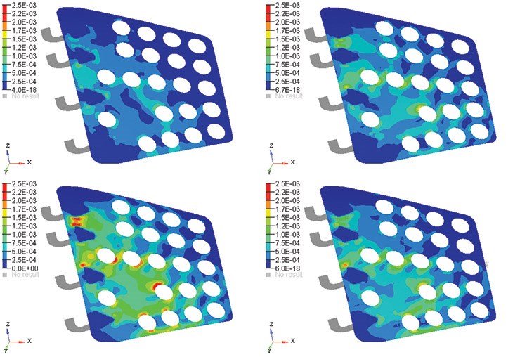
Atkins compared a number of sandwich panel configurations, in terms of skin and core thickness, with the solid aluminum (Figs, 1 & 2, at left). “Early analysis showed that in the composite designs, the maximum deflection was occurring at the corner furthest from the actuator attachment,” says Edwards, “We had to increase overall stiffness, and the potential composite layups were altered to include a greater number of ±45° plies.” This strategy was confirmed by the modal analyses (a study of how the doors would react under vibrational excitation), using the Radioss solver in Altair’s HyperWorks software package. The first vibrational mode was torsional, meaning that the door’s trailing edge would have a tendency to twist relative to the hinge line. This reinforced Edward’s conclusion that more bias plies were a must.
The Atkins team ultimately developed four door designs: 1) a single aluminum piece, 40 mm thick; 2) a composite sandwich panel with 6-mm UD facesheets and 38-mm-thick core; 3) a composite sandwich with 7-mm woven prepreg facesheets with 36-mm-thick core; and 4) a composite sandwich with 7-mm-thick facesheets made up of a combination of UD tapes and woven fabric prepreg, with a 38-mm-thick core. The 7-mm facesheet requires an approximate 28-ply layup.
Edwards makes clear that the aluminum design exhibited the smallest maximum deflection. But, in addition to weighing almost four times more than the composite solution (70 kg vs. 19 kg), it exhibited a much lower first natural frequency (61 Hz), indicating a propensity for undesirable vibration when deployed. Fig. 2 shows the four designs in terms of maximum strain results; Edwards points out that while stress concentrations occur at hole edges closest to the actuator arm, the use of ±45° plies increased the first natural frequency and reduced overall strain values. “We conducted Tsai-Hill ply failure analysis in the FEA solver to ensure that there were no predicted failures in the higher strain regions,” he says, concluding, “The cored composite is the most structurally efficient design.” Edwards notes that Bloodhound engineers will make the final selection from among the three cored designs.
An opportunity for STEM students
The impending run at the 1,000-mph threshold has captured the imagination of thousands of followers. Noble is keen to lift awareness in UK schools and stimulate student interest, using a wide range of math and engineering problems related to the car’s design. In fact, Bloodhound team members regularly lecture in schools, and post math questions online about vehicle systems. When Edwards visited Seattle to deliver a presentation at the SAMPE conference in May 2014, he also gave a talk on propulsion to students at nearby Raisbeck Aviation High School. And student teams in the UK are even building rocket-powered scale models of the Bloodhound.
Provided that Hakskeen Pan is dry and ready, the Bloodhound’s first high-speed runs could commence late this year. Edwards says these will take the car up to around 800 mph, which in itself would be a world record. Low-speed UK runway tests are scheduled for earlier in 2015. The full-on “1,000” run likely will occur sometime in 2016. Bloodhound’s driver, Andy Green, has said in his monthly diary, “It’s easy to forget the most important part of building the world’s first 1,000-mph car: Getting to 1,000 mph safely is not just about technology, it’s about engineering expertise ….” The world will be watching this engineering marvel in its record quest.
See an animation of the Bloodhound SSC air brakes in action on the Bloodhound Web site.
See a recent math exercise about the Bloodhound SSC air brake system posed for students — and the answer — on the team’s Web site.
The Bloodhound SSC Web site also has an extraordinary amount of information, including all CAD drawings, for the vehicle and its systems, here.
Related Content
Aptera joins forces with C.P.C. Group to accelerate solar EV production
Specialized composite bodies are being produced in Modena, Italy, for Aptera’s BinC vehicle, enabling eventual manufacturing ramp-up of 40 vehicles/day to meet demand targets.
Read MoreSABIC launches fiber-reinforced, intumescent, fire-retardant resins
SABIC PP compound H1090 and Stamax 30YH611 resins are well suited for extruding and thermoforming large, complex EV battery pack components for automotive.
Read MoreSMC composites progress BinC solar electric vehicles
In an interview with one of Aptera’s co-founders, CW sheds light on the inspiration behind the crowd-funded solar electric vehicle, its body in carbon (BinC) and how composite materials are playing a role in its design.
Read MoreAptera reveals first composite production parts for BinC vehicle
Pre-production efforts are underway to begin building production-intent vehicles.
Read MoreRead Next
“Structured air” TPS safeguards composite structures
Powered by an 85% air/15% pure polyimide aerogel, Blueshift’s novel material system protects structures during transient thermal events from -200°C to beyond 2400°C for rockets, battery boxes and more.
Read MoreVIDEO: High-volume processing for fiberglass components
Cannon Ergos, a company specializing in high-ton presses and equipment for composites fabrication and plastics processing, displayed automotive and industrial components at CAMX 2024.
Read MoreDeveloping bonded composite repair for ships, offshore units
Bureau Veritas and industry partners issue guidelines and pave the way for certification via StrengthBond Offshore project.
Read More



.jpg;maxWidth=300;quality=90)

