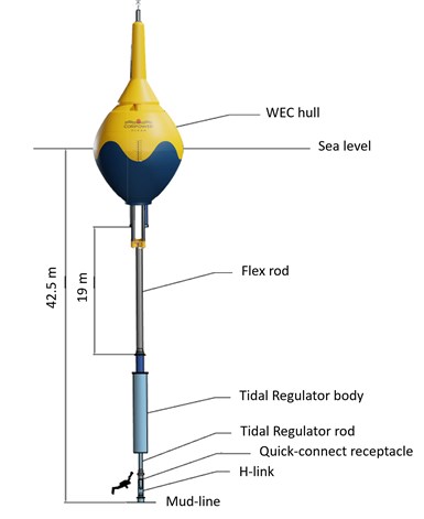
Updated, spherical design. CorPower Ocean’s Wave Energy Converter (WEC) has undergone several design iterations as the company works to test and scale up its ocean energy technology for industrial-scale renewable energy. The first full-scale prototype of this most recent, sphere-shaped iteration, called C4, is set to be deployed for ocean testing by the end of 2021. Photo Credit, all images: CorPower Ocean
As of the end of 2020, global cumulative energy capacity from ocean energy (combining both wave energy and tidal energy) reached approximately 65 megawatts (MW), a figure that has more than doubled since 2017, according to the latest report from Ocean Energy Systems (OES), an intergovernmental collaboration under the International Energy Agency (IEA, Paris, France). However, there’s still a long way to go to reach OES’ goal for global ocean energy capacity to reach 300 gigawatts (GW) by 2050.
One promising ocean energy technology is wave energy converters (WEC), devices that use the motion of ocean waves to generate electricity. Various types of WECs have been developed, and many of these concepts work in a similar way to hydroelectric turbines: A column-, blade- or buoy-shaped device sits on top of or under the water, where they capture the energy generated by ocean waves acting on the device. That energy is then transferred to a generator that converts it to electricity.
Ocean waves are relatively uniform and predictable, but wave energy — like most other types of renewable energy, including solar and wind — is still a variable energy source, producing more or less energy at different times based on factors such as wind and weather conditions. Therefore, two key challenges to designing reliable and competitive WECs are durability and efficiency: The system needs to be able to survive large ocean storms, and to efficiently capture energy during optimal conditions in order to meet annual energy production (AEP) targets and drive down the cost of electricity.
The first full-scale prototype of WEC developer CorPower Ocean’s (Stockholm, Sweden) 9-meter-diameter spherical buoy WEC is expected to be installed for its first ocean trial by the end of this year. In designing the system, the company discovered that filament-wound glass fiber composites were the most efficient, most cost-effective solution to manufacture its large buoy hulls. After several years of subscale testing, the first full-scale prototype is being manufactured via a bespoke filament winding system developed in cooperation with Autonational BV (Iljst, Netherlands).
Designing a composite-hulled WEC: Light weight, high efficiency
The full-scale prototype will be ready for launch in late 2021, but CorPower Ocean has been developing the system since 2011, when Swedish inventor and cardiologist Stig Lundbäck hatched the initial idea for an energy-capturing buoy system modeled after the pumping principles of the human heart. A structured product development program was initiated in 2011 when Lundbäck teamed up with technology entrepreneur Patrik Möller, who became CorPower Ocean’s CEO.
Inside the blue-and-yellow-painted composite hull of CorPower’s WEC is the system that converts the buoy motion into electricity. A pneumatic pre-tensioning unit uses pressure to balance the buoy on the water. When a wave pushes the buoy upward, the system stores the energy as pressurized air, which is then used to drive the buoy downwards (similar to how a human heart stores and flows energy as it pumps), resulting in equal energy produced in two directions that is converted into electricity by an electromechanical drivetrain inside the buoy (see more in video below). A control system, added to the WEC design in 2014 through a collaboration with researchers at the Norwegian University of Science and Technology (NTNU, Trondheim), is said to amplify the power capture from this system. Each device is designed to deliver 300 kilowatts (kW) of energy.
The hull itself “is equivalent to the blade of a wind turbine. It’s what extracts the energy from the ocean waves and transfers it to the powertrain,” explains Javier Verdeguer, senior composite design engineer at CorPower Ocean.
One of the core requirements of the WEC system is light weight, Verdeguer says. During regular conditions, a lighter device is able to be more easily controlled and can absorb more power, and in storm conditions, it helps avoid high loads on the system. Durability is also an important factor: The WECs are designed for an overall lifecycle of more than 20 years, with scheduled maintenance every five years.
The hull was designed using SolidWorks software (Dassault Systèmes, Waltham, Mass., U.S.), followed by CadFil (Kegworth, U.K.) for the composite winding path design, Ansys software (Canonsburg, Pa., U.S.) for structural assessment and Orcaflex (Orcina, Ulverston, U.K.) for motion and loads. According to Möller, a proprietary wave-to-wire numerical modeling tool was used to determine and simulate device motion including non-linear losses, real-time control of motion damping and non-linear hydrodynamics.
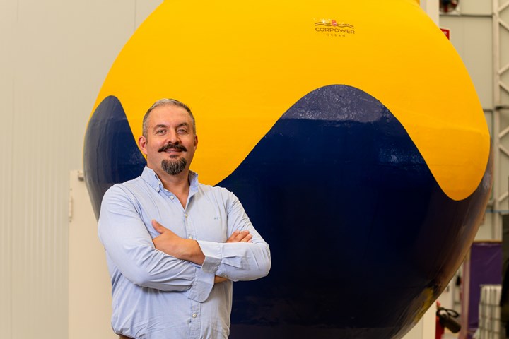
Industrial-scale wave energy, filament-wound composites. CorPower Ocean aims to install its first full-scale wave energy converter (WEC) prototype (shown here as a 1/4-scale model) for ocean trials by the end of this year. Pictured here is Miguel Silva, managing director of CorPower Ocean Portugal and leader of the company’s composites efforts. Photo Credit, all images: CorPower Ocean
HiWave-3, funded by InnoEnergy, Wave Energy Scotland and the Swedish Energy Agency, was a three-year demonstrator project (2015-2018) to manufacture and dry test a half-scale WEC prototype, called C3. This development guided the design of C4, the first full-scale system that is set to be installed this year.
Early in the design phase, CorPower Ocean performed a cost analysis to compare and evaluate steel, aluminum and composite hull options, looking at both annual energy production (AEP) of the device and cost-effective manufacture. After evaluating several subscale models, filament winding proved to be the lightest material with the most cost-effective manufacturing process, Verdeguer says.
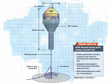
Iterating the design. The original C3 design featured a cylindrical hull. Each round of testing has brought about new insights and design innovations.
Originally, the design was a cylindrical-shaped, single-skin composite hull. Between the C3 and C4 design iterations, four tank test campaigns using scale models of the hull and mooring system were performed, as well as digital simulations, and the team ultimately decided to evolve the design into a spherical hull shape, which distributes stresses more evenly along its surface, and sandwich construction. “A sphere is the structurally strongest shape you can have to take external hydro pressure [from ocean waves],” Möller explains.
The current C4 iteration of the device is 19 meters tall and divided into two components: A 9-meter spheric main body or hull, and a 10-meter column, which is anchored to the ocean floor via a tensioned mooring system. The hull is a sandwich component filament wound around a 10-meter-long mandrel; this includes an inner skin combining glass fiber rovings and specially developed 141-millimeter-wide bands of fabric, a layer of Diab (Helsingborg, Sweden) Divinycell H structural core designed for strength and to adapt to the curvature of the hull, and an outer skin also comprising filament-wound rovings and fabric. “We have been working closely with CorPower to find the best solution for the core material, to ensure durability and a long lifetime for a structure exposed to harsh conditions,” says Lars-Magnus Efraimsson, market segment manager at Diab.
The overall thickness of the part is about six centimeters. After filament winding, each hull is cured at room temperature before mechanical systems, ladders and other components are assembled, and the final hull is coated with a gel coat for UV protection.
“There are, of course, multiple things we still need to prove out [through ocean testing], but we have a very good composite hull concept with high structural efficiency,” notes Tord Jonsson, supply chain and quality manager at CorPower Ocean.
Mobile, large-scale, automated filament winding
Once composites were decided upon for the design, one challenge was finding a manufacturing process capable of building the large, rounded, hollow structure. According to Jonsson, manufacture via filament winding proved to be more cost-effective and faster than manufacturing a metal component. CorPower aims to be able to produce one buoy per filament winding cell in about 48 hours, he says, adding, “Being able to manufacture at high speeds with highly precise lay-down of the fibers is quite important, and we can achieve that with filament winding.”
A typical filament winding system would typically be permanently installed in a factory environment, explains Harry Fietje, marketing and sales manager at Autonational BV. However, given the size of the buoys, transportation costs and related CO2 emissions would be high if CorPower were to transport the hulls from a central manufacturing site to global installation sites, so the company began to search for a manufacturing process that would allow them to quickly produce buoys in local facilities set up near deployment sites. There are several mobile filament winding systems on the market already, Fietje says, but many of these can also be difficult and expensive to transport.
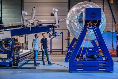
Flexible, mobile filament winding. A bespoke filament winding system developed with Autonational BV (pictured here at Autonational’s Netherlands facility testing a subscale model) is capable of winding a four-material, 9-meter-diameter hull, as well as easy transport between mobile facilities.
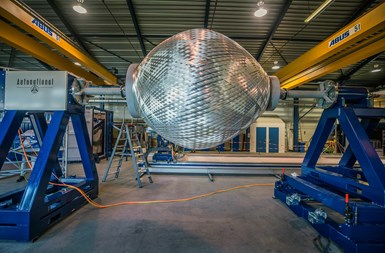
In partnership with CorPower Ocean, Autonational’s engineering department developed its own mobile system, consisting of a filament winder situated on a 45-foot-long base that also serves as the bottom half of a shipping container. When transport is required, the entire winder can be rotated 90 degrees to fit into the base container, with a lid closing over top of it. The resulting system is easily transported via boat or truck to the shoreline sites where CorPower will be producing buoys, and then set up in a matter of two days or less, Fietje says. “The challenge was in making sure the filament winding system was as strong and functional as a typical system installed in a factory, but making it light and mobile,” he says. “It’s something that’s never been done before, as far as I know.”
The filament winder itself includes an automated carrying system for putting the fibers onto a 10-meter-long, 9-meter-diameter mandrel. “Normally, you only need 1-3 meters, but this buoy is exceptionally big in diameter,” Fietje says. In addition to wet winding with rovings and fabric, the system is also able to spray chopped fiberglass and insulating foam. The foam can be sprayed onto a pre-wound inner skin, then machined to shape and wound with material again for the outer skin. “Normally you only have one or maybe two materials you want to use, but these buoys require the system to use [up to] four types of materials from the same machine,” he says.
Due to the size of the system, special accommodations had to be included such as steps for a human operator, and five cameras installed on the delivery tool, resin impregnation system, bobbins and creels to enable the operator to see all parts of the machine at once. Sensors, such as encoders and inductive sensors, were also embedded to control resin temperature. The filament winding machine also features a removable tail stock for easy part removal.
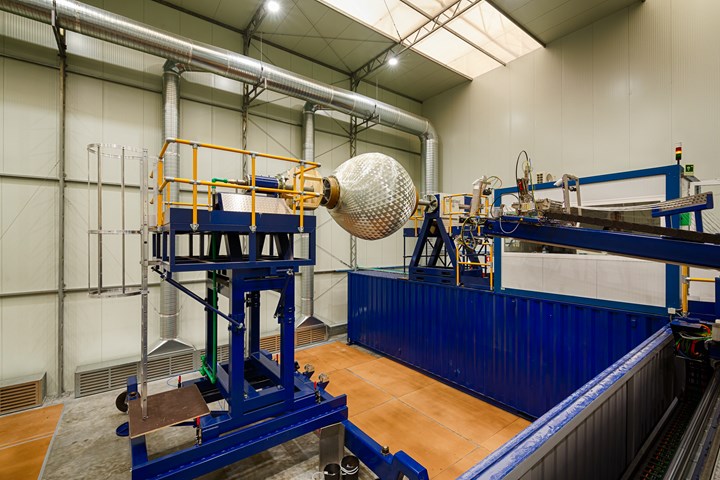
Prepping for full-scale. Pictured here, the winder was transported by truck to CorPower Ocean’s Portugal-based mobile factory to build the first full-scale prototype. Ultimately, CorPower plans to install and run several mobile winders simultaneously to quickly produce WEC farms with thousands of units.
The development of the winding machine, Fietje says, involved much communication back and forth between Autonational and CorPower. “We were working on the machine at the same time that they were working on their prototype design, so new functionalities ended up being added as their design evolved,” he explains.
“Autonational was not just a machine supplier; they were very much a speaking partner with us, helping and guiding us to different technology solutions to enable this very large machine, which is the largest one they’ve ever made. It was also important to us for it to be the very flexible machine that it is, to accommodate any new materials or design changes that we may have,” Jonsson says.
HiWave-5: Next stage toward commercialization
After proving out the machine at Autonational’s facility, the final winder was transported via truck to a temporary production facility in Viana do Castelo, Portugal, for HiWave-5. The HiWave-5 demonstration project, begun in 2018, aims to build, dry test, certify and ocean test full-scale WECs. Currently, CorPower Ocean is in stage four of the five-stage project, targeting ocean testing of the C4 prototype. In stage five, three additional full-scale WECs, called C5, will be built and deployed by 2023.
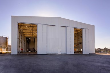
First mobile factory. CorPower Ocean constructed this temporary production facility in northern Portugal. Here, the WEC hull is manufactured, the rest of the components are assembled and the WEC is ready to be deployed off the coast nearby.
“We have followed a stepwise approach to developing our products, and we go through a very extensive dry testing campaign before anything is installed in the ocean,” Verdeguer says. Prior to integration with the hull and installation in the ocean, for example, the buoy’s internal drivetrain is tested and stabilized at CorPower Ocean’s Sweden facility, in an on-land test rig that simulates wave loads up to those that would be experienced in worst-case storm conditions.
For HiWave-5, CorPower Ocean has invested in an on-land facility housing the mobile factory cell for composite hull winding as well as final assembly and maintenance of the WEC system located in the commercial port of Viana do Castelo in northern Portugal.
Global installation: Working together with offshore wind energy
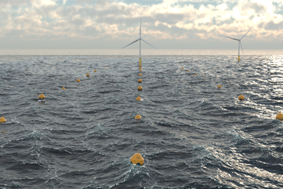
Ultimately, CorPower’s WEC is designed for installation in offshore farms of hundreds or even thousands of units, and can be co-located with offshore wind farms. Jonsson notes that there are benefits to “using our technology in combination [with other forms of renewable energy] for reducing costs related to the electrical export infrastructure of combined farms, definitely, but also the combination will reduce variability of the power production to give farm owners a more valuable product to help enable transition to fully decarbonized energy systems in a reliable way.” According to CorPower Ocean, its WEC devices can provide up to five times more energy output per metric tonne than competitive wave energy technologies, bringing wave energy to a similar level of structural efficiency as offshore wind.

Combining renewable energy sources. This simulation demonstrates CorPower Ocean’s ideas for deploying WEC farms nearby offshore wind farms, to reduce infrastructure costs and complement wind energy.
Upon the successful completion of HiWave-5, CorPower Ocean plans to install its first commercial farm of 15-30 units in 2025. From there, CorPower Ocean will increase the size of the farms and begin to install buoy systems globally, setting up mobile factories like the one currently set up in Portugal for on-site manufacture and assembly. “That’s why we developed this mobile machine with Autonational, so we can pack it in three containers and ship it to any location around the world,” Jonsson says. “We make the hull on site, then integrate the drivetrain and other internal mechanical parts, and we’re ready to deploy it while the winding cells are moved on to the next customer site.”
Alongside commercial installation, CorPower Ocean also aims to reduce costs, targeting levelized cost of energy (LCOE) of less than 40 euros per megawatt-hour. As the technology moves forward, Jonsson expects they will be able to optimize materials, design and processes further as well, to increase the efficiency of the devices.
Verdeguer adds, “Our ultimate goal is that our technology would complement wind and solar, providing the lowest cost and most reliable path for the world to achieve 100% renewable energy systems.”
Related Content
The potential for thermoplastic composite nacelles
Collins Aerospace draws on global team, decades of experience to demonstrate large, curved AFP and welded structures for the next generation of aircraft.
Read MoreASCEND program update: Designing next-gen, high-rate auto and aerospace composites
GKN Aerospace, McLaren Automotive and U.K.-based partners share goals and progress aiming at high-rate, Industry 4.0-enabled, sustainable materials and processes.
Read MoreCryo-compressed hydrogen, the best solution for storage and refueling stations?
Cryomotive’s CRYOGAS solution claims the highest storage density, lowest refueling cost and widest operating range without H2 losses while using one-fifth the carbon fiber required in compressed gas tanks.
Read MorePlant tour: Albany Engineered Composites, Rochester, N.H., U.S.
Efficient, high-quality, well-controlled composites manufacturing at volume is the mantra for this 3D weaving specialist.
Read MoreRead Next
Hydroelectric turbine blade design propelled by composites
Glass fiber composites power the development of a modular, spiral-shaped hydroelectric micro turbine blade for low-cost, high-efficiency renewable energy generation.
Read MoreComposites-intensive wave energy technology receives new funding
CorPower Ocean and OPS Composite Solutions secure almost €500,000 from EEA grants to advance buoy-based renewable energy technology.
Read MorePlant tour: Daher Shap’in TechCenter and composites production plant, Saint-Aignan-de-Grandlieu, France
Co-located R&D and production advance OOA thermosets, thermoplastics, welding, recycling and digital technologies for faster processing and certification of lighter, more sustainable composites.
Read More

.jpg;width=70;height=70;mode=crop)


.jpg;maxWidth=300;quality=90)


