
Mechanical wedge grips for tensile testing
In tensile testing, wedge grips are used on both ends of the specimen to position the specimen in the test frame.


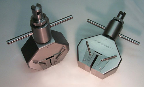
Fig. 2: A pair of 30-kip standard grips. Source: Don Adams
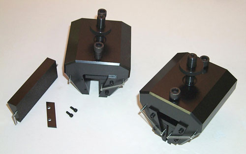
Fig. 1: A pair of simple grips with top-mounted wedge insert tighteners. Source: Don Adams

Dr. Donald F. Adams is the president of Wyoming Test Fixtures Inc. (Salt Lake City, Utah). He holds a BS and an MS in mechanical engineering from, respectively, the University of Illinois and the University of Southern California, and a Ph.D in theoretical and applied mechanics from the University of Illinois. Following a total of 12 years with Northrop Aircraft Corp., the Aeronutronic Div. of Ford Motor Co. and the RAND Corp., he joined the University of Wyoming, directing its Composite Materials Research Group for 27 years before retiring from that post in 1999. Dr. Adams continues to write, teach and serve with numerous industry groups, including the test methods committees of ASTM and the Composite Materials Handbook 17 (CMH-17).
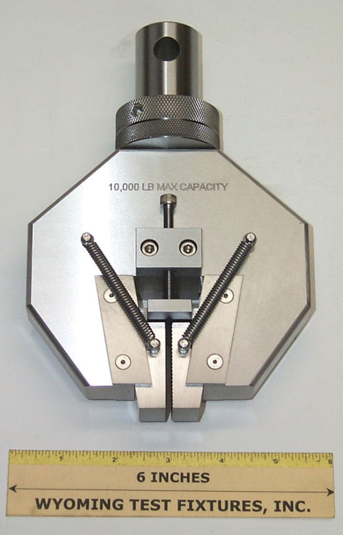
Fig. 3: Simple grip with side-mounted wedge insert tighteners. Source: Don Adams
In tensile testing, wedge grips are used on both ends of the specimen to position the specimen in the test frame. Wedge grips incorporate two main components: the grip body and two grip inserts, as seen in Fig. 1. They function, as the name implies, by the wedging action induced as the opposing grip inserts slide in relation to the angled interior walls of the grip body. The gap between the inserts decreases, applying clamping force to the test specimen, during initial specimen installation and subsequent axial loading.
There are three types of wedge grips: mechanical (pictured in the figures below), hydraulic and pneumatic. Each type has its relative advantages and disadvantages. However, because mechanical grips tend to be less expensive and bulky, and simpler to use, they are used much more extensively. For this reason, they will be the focus here.


There are two basic subcategories of mechanical wedge grips, which, for lack of established terminology, will be referred to here as “simple” grips (Figs. 1 & 3) and “standard” grips (Fig. 2). The types are distinguished by the method used to open and close the grips. Simple grips are designed such that the grip inserts move and the grip body remains stationary as the grips are tightened onto the test specimen. That is, the grip body is directly linked to the testing machine attachment points and remains stationary.
In the simple grip in Fig. 3, a screw on each side of the grip is turned to force the grip inserts against the specimen and hold it in place until the testing machine force is applied. The springs hold the inserts against the push plate and also retract the inserts as the grips are opened. In the simple grip in Fig. 1, one grip insert has been removed to better show the detail of the insert. For these wide grips, the tightening screws are located on the top of the grip body. However, the principle of operation is the same as for the simple grips of Fig. 3. Although there exist many design variations for simple grips, in all designs, the inserts (not the grip body) move during opening and closing.
In the standard grip, the grip body moves axially and the grip inserts remain stationary. This design feature is achieved by linking the grip inserts directly into the load train. That is, the grip inserts are directly linked to the testing machine attachment points. In Fig. 2, a threaded rod or axle links the cylindrical section or collar on top to the two inserts at bottom, which remain stationary during test specimen installation. Handles, such as those shown, are commonly used to turn the collar, drawing the body away from the specimen.
Simple grips, as the name implies, are easier to fabricate and typically 20 to 30 percent less expensive than the standard grip. This fact alone accounts for their popularity. However, when simple grips are installed in the test frame and one end of the specimen is secured in the first grip, axial movement of the second grip’s inserts can induce an undesired axial compressive force in the specimen as they are tightened. This could damage the specimen. This risk is avoided when standard grips are used because the inserts apply clamping pressure without moving axially.
It is possible, with simple grips, to avoid this problem by using the following installation procedure: After the lower grip is firmly clamped on the specimen, the upper grip should be tightened only enough to hold the weight of the lower grip. At this point, the lower grip body can be disengaged from the load train, freeing it to move axially. Then the upper grip can be tightened further without inducing a compressive load. After the upper grip is fully installed, the lower grip is reattached to the load train. Often, simple grips are configured to attach to the testing machine using stud and socket connections, which are pinned together (see end note). The pin can be removed prior to final tightening and then reinserted after tightening the upper grip and realigning the holes at the lower grip by moving the testing machine crosshead. That said, this procedure obviously is inconvenient and time-consuming, a fact that could justify an investment in the more costly standard grips.
Regardless of grip type, the wedge angle is typically small, in the range of 10°. Because the wedge inserts and body must slide relative to each other in the process of opening or closing, simple math shows that the range of opening is limited. For most grips this range is on the order of 6 mm/0.25 inch. Therefore, it is often necessary to purchase multiple sets of grip inserts with each pair of grip bodies. The insert sets, made in different thicknesses, each operate over a specified portion of a much wider range.
Another insert selection factor is the type of insert face to use when testing a particular material. Insert faces that incorporate machined serrations have been in common use for a long time. The faces can have either straight serrations, perpendicular to the load direction, or crosshatched serrations, with the serrations oriented at either ±θ in relation to the load direction, or 0° and 90°. Serration pattern selection depends on the degree of surface damage the specimen can sustain without affecting the measured tensile strength and whether or not the specimen gripping surfaces are flat and parallel. Straight serrations are typically very aggressive and bite deeply into the specimen surfaces. This gives them good holding power and compensates for specimen surface irregularities. However, it might be necessary to tab the test specimen (that is, adhesively bond a protective layer of material to each region that will be in contact with the grip inserts). Crosshatched serrations are not as aggressive but can have equally high holding power if the specimen surfaces are not too irregular. Less aggressive grip faces can be obtained by partially filling the serrations so that the depth they can penetrate into the specimen surface is reduced. This is often achieved by placing emery cloth (with the abrasive side facing the specimen) or some other material between the grip faces and the specimen.
A more recently developed alternative to serration is to coat the insert faces with tungsten carbide particles in the range of 60- to 100-grit. On relatively flat and parallel specimen surfaces, these grips can have holding power equivalent to the serrated grips but cause little damage to the specimen surfaces, so tabbing or other protection of the specimen might not be necessary. However, if the specimen surfaces are irregular, the grip faces will contact only the high spots and grip less effectively.
Ultimately, the choice between simple and standard grips is more of an economic than a technical issue. Simple grips, ironically, complicate specimen installation. Standard grips, though more expensive, simplify installation and, therefore, are the option I would recommend.
Dr. Adams wrote about stud-and-socket-type testing machine connectors previously in “Testing Tech.” See "Learn More," at right.


.jpg;maxWidth=300;quality=90;format=webp)


Related Content

Measuring ply-wise deformation during consolidation using embedded sensors
Strip-type shape sensor method claims real-time measurement of ply-wise deformation.
Read More
Crashworthiness testing of composites: A building block approach, Part 1
Determining the crashworthiness of composite structures requires several levels of testing and analysis, starting with coupon-level crush testing.
Read More
Notched testing of sandwich composites: The sandwich open-hole flexure test
A second new test method has been standardized by ASTM for determining notch sensitivity of sandwich composites.
Read More
Composite test methods (and specifications) for fiber-reinforced concrete structures
While initially focused on transitioning existing standards published by the American Concrete Institute, the relatively new ASTM Subcommittee D30.10 is developing new standardized test methods and material specifications for FRP composites.
Read MoreRead Next

Testing Tech: Test fixture and testing machine adapters
In preparation for testing, typically the upper portion of the test fixture is connected to a load cell in the crosshead of the testing machine, and the lower portion of the fixture is connected to the base of the machine.
Read More
Plant tour: Daher Shap’in TechCenter and composites production plant, Saint-Aignan-de-Grandlieu, France
Co-located R&D and production advance OOA thermosets, thermoplastics, welding, recycling and digital technologies for faster processing and certification of lighter, more sustainable composites.
Read More
VIDEO: High-volume processing for fiberglass components
Cannon Ergos, a company specializing in high-ton presses and equipment for composites fabrication and plastics processing, displayed automotive and industrial components at CAMX 2024.
Read More