Crashworthiness testing of composites: A building block approach, Part 1
Determining the crashworthiness of composite structures requires several levels of testing and analysis, starting with coupon-level crush testing.
Figure 1. Building block approach for crashworthiness-related testing associated with composite structures. Source (All Images) | Dan Adams
Crashworthiness may be defined as a structure’s ability to provide controlled energy absorption and protect its occupants from excessive forces and peak accelerations in a crash. In general, the choice of both materials and geometric configuration influences a structure’s crush failure mechanisms and overall energy absorption capability. For most of us, the structures for which crashworthiness is most familiar are our cars and trucks.
Unlike metals, which absorb energy primarily through plastic deformation, polymer matrix composites (PMCs) absorb energy through brittle fracture of the fibers and the matrix. When properly designed, composite structures can remain intact and enable crush failure to occur in a stable and progressive manner. Moreover, in comparison to metals, PMCs have been shown to produce increased energy absorption per unit mass, referred to as specific energy absorption, due to their relatively low density and their ability to absorb energy through progressive crush. In general, energy absorption capabilities of PMCs are dependent on the fibers and matrices used, the laminate configuration (ply orientations and stacking sequence) and the design of the composite structure.
Previously discussed in my August and December 2021 CW columns, a building block approach is a step-by-step process that serves as a framework for designing composite structures while also reducing risk and cost. An example of a building block pyramid, illustrating the levels of crashworthiness-related testing associated with a composite aircraft structure, is shown in Fig. 1. For composite structures with crashworthiness requirements, the complexity of testing and analysis increases whereas the number of tests decreases when moving up to a higher building block level. Currently, the most extensive coverage of this crashworthiness building block approach for composites is provided in volume 3, chapter 16 of the “Composite Materials Handbook-17 (CMH-17).”1
In this column, I’ll focus on the base level of this building block pyramid, in which a majority of the coupon-level crush testing is performed for screening composite materials and laminates. These tests provide estimates for laminate crush stress and specific energy absorption (SEA), defined as energy absorption per unit mass of crushed material. The higher levels of this building block include element level, subcomponent level and full-scale level crush testing performed to investigate the crashworthiness of specific portions of a proposed composite structure. These higher building block levels will be discussed in my next column.
Flat-coupon crush testing of stanchion elements
When beginning to assess the crashworthiness of a composite structure, coupon-level test articles are typically chosen to represent key portions of the intended composite crush structure. Within the automotive industry, composite tube segments have been used as coupon-level test articles, following the practice of using tube-like metallic structures that absorb energy when compacted in a relatively stable, accordion-like manner. Such tube segments are self-supporting test articles and therefore do not require elaborate test fixturing when performing crush testing.
In recent years, the Crashworthiness Working Group of CMH-17 has focused on the use of flat-coupon crush testing to measure laminate-level crush properties and to screen candidate composite laminates for energy absorption. One reason for the use of flat specimens was the intended application: C-channel shaped composite stanchions that support the floor beams in a transport aircraft fuselage as shown in Fig. 2. In addition to serving as structural members during normal aircraft operations, these stanchions have also been identified as principal energy-absorbing structural elements. The cross section of a typical C-channel stanchion, as shown in Fig. 3, is composed of a central web section and two outer flange sections connected through two corner regions. Such C-channel stanchions provide structural stability and permit flush attachment to adjoining flat structures in an aircraft fuselage.
The CMH-17 Crashworthiness Working Group’s recent focus has been the crush testing and numerical crush simulation of these composite stanchions. Efforts to date have been devoted to the coupon and element levels of the building block. At the coupon level, flat-coupon crush testing was performed to establish the laminate-level crush response of selected carbon fiber/epoxy laminates. An advantage of using flat coupons is that they can be cut from flat panels, similar to other mechanical test specimens, thus greatly simplifying fabrication. Similar to composite compression test specimens, however, these flat crush test specimens must be supported during crush testing to prevent buckling.
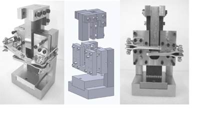
Collaborative research performed by Engenuity Ltd.2 (West Sussex, U.K.) and the University of Utah3-4 (Salt Lake City, U.S.) resulted in test fixturing, a common specimen geometry, and a test procedure for flat-coupon crush testing. The Utah flat-coupon crush test fixture3, developed for such testing is shown in Fig. 4. The upper support of the test fixture end-loads the flat coupon against the fixture base, and the lower support prevents the coupon from buckling. The upper and lower supports are adjustable to permit the crush testing of various coupon thicknesses and gage lengths. Both unsupported and pin-supported test fixture bases (Fig. 3) are used to characterize the flat and curved regions of the crush structure, respectively. The unsupported base enables the flat coupon to crush freely, whereas the pin-supported base constrains the flat coupon from out-of-plane deformation and splaying.
Based on initial stress analyses5, the 16-ply laminate configuration selected for use in the C-channel stanchion consisted of eight 0° plies, four ±45° plies, and four 90° plies. From this laminate configuration, five ply stacking sequences were selected for flat-coupon crush testing based on prior crush testing results using similar carbon fiber/epoxy laminates:
- [902/±45/04]S Stiffest plies at midplane
- [902/02/±45/02]S High SEA in previous study
- [90/+45/02/90/-45/02]S Ply dispersion while maintaining SEA
- [±45/902/04]S Outer 45° plies, high SEA in previous study
- [±45/90/0/90/03]S Outer 45° plies, greater ply dispersion
Based on the results of the flat-coupon crush testing, two laminates were selected for follow-on C-channel crush testing: [902/02/±45/02]S and [90/+45/02/90/-45/02]S. Both laminates demonstrated high energy absorption using the unsupported and pin-supported base plates. Note that both laminates have a total of four 0° plies grouped at the laminate midplane, which served to promote fragmentation failure, a high energy-absorbing failure mode, during crushing.
Following flat-coupon crust testing, results were provided to Crashworthiness Working Group members for use in performing initial crush analyses. Such coupon-level crush analyses permitted the estimation of modeling parameters and properties used in modeling progressive crushing at higher building block levels. At the element level, the analysis teams performed crush test simulations of the C-channel stanchion and provided blind predictions of the crush behavior prior to being provided with crush test results. Therefore, these initial numerical analyses provided an initial assessment of the numerical analysis method and the input parameters selected.
A subsequent column will address element-, subcomponent- and component-level testing in a composite crashworthiness building block approach.
References
1“Composite Materials Handbook - 17 (CMH-17),” Volume 3, Chapter 16: Crashworthiness and Energy Management, SAE International, Rev. H, 2025.
2 Engenuity Ltd., West Sussex RH15 8RG, U.K. Retrieved from www.engenuity.net/
3 Hobbs, J. M., “Effects of Laminate Design on the Crashworthiness of Carbon/Epoxy Composite Materials” Ph.D. Dissertation, University of Utah, May 2019.
4 Ostler, D. W., “Characterization of Carbon/Epoxy C-Channels for Crashworthiness Applications,” M.S. Thesis, University of Utah, May 2021.
5 Altair Engineering (n.d.). Retrieved from www.altair.com/
Related Content
Numerical tool with mean stress correction demonstrated for fatigue life estimation of thermoplastic composites
To aid design of fatigue-resistant structures, Econ Engineering has developed an algorithm to evaluate ply-based cyclic stiffness degradation combined with an FE failure check, validated for a CF/PAEK pressure vessel.
Read MoreDamage tolerance testing of sandwich composites: The sandwich CAI test
A new ASTM-standardized test method established in 2022 assesses the compression-loaded damage tolerance of sandwich composites.
Read MoreDamage tolerance testing of sandwich composites: The sandwich flexure-after-impact (FAI) test
A second new ASTM-standardized test method assesses the damage tolerance of sandwich composites under flexural loading.
Read MorePhotothermal tomography for locating, quantifying defects in composites
Years of infrared testing development result in thermography technology that is no longer just qualitative, but can define defect size and depth, making additional UT scans obsolete.
Read MoreRead Next
Avoiding pitfalls in the design of LFAM composite components
Recoat temperature, part orientation and bead geometry are some key design variables to consider for a successful and reliable large-format additive manufacturing (LFAM) process.
Read MoreThe FAA: Keeping up with aerocomposites evolution
Composite and metallic structures must conform to the same performance-based standard of safety.
Read MoreTesting the crashworthiness of composite structures
Dr. Donald F. Adams examines automobile crashworthiness, noting popular crashworthiness test methods for composites, and points out the lack of, and current progress toward, standardized testing for composite crash structures.
Read More


