Megayacht Composite Masts Get Smart
Freestanding square rigging is fully instrumented for structural health monitoring while under sail.
Share
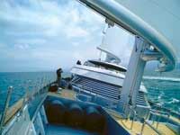
Launched in July 2006, the Maltese Falcon superyacht, owned by wealthy former Hewlett-Packard principal Tom Perkins, captures a lot of “firsts.” It is one of the largest privately owned vessels in the world and arguably the most technologically advanced sailing yacht — at launch, the 87.5m/289-ft, three-masted steel-hulled craft was the world’s largest in terms of displacement, but since has been surpassed by the schooner Eos. It is the first large square-rigger to be equipped with freestanding masts — that is, masts that require no cable support — and also is the first with masts that are fully instrumented with embedded fiber-optic sensors, which monitor strains for optimal sailing. The unique rigging system, an all carbon/epoxy composite design, is the end product of an incredibly detailed and multifaceted design and manufacturing process, says Damon Roberts of Insensys Ltd. (Hamble, Southampton, U.K.), who headed the effort. The project required extensive finite element modeling and analysis, structural testing of prototypes, wind tunnel and tank tests as well as operational sailing with subscale models. “We essentially undertook a comprehensive risk reduction program to ensure the free-standing composite mast and rig concept would work,” says Roberts.
A new breed of square-rigger
While slender 19th Century square-rigged clipper ships provided the inspiration, says Roberts, he and naval architect Gerard Dijkstra of G. Dijkstra and Partners (Amsterdam, The Netherlands) focused the design on a more modern approach — the DynaRig concept. Developed in the mid-1960s by German inventor and environmental advocate W. Proelss, DynaRig was envisioned as a fuel-saving, large-scale sail propulsion system for commercial vessels, featuring rotating masts and automated sail furling/unfurling systems that would maximize efficiency. Proelss died in 1974 before the concept could be realized, stymied by significant technical issues, not the least of which was how to achieve sufficient bending stiffness in a metallic mast constructed with a large lengthwise slot to accommodate the automatically furling sails, without resorting to supporting cable stays.
High-strength composites have since provided the solution. In fact, freestanding composite masts had been developed and validated by Insensys on smaller racing yachts, but not on the scale of the Maltese Falcon, says Roberts. “The extrapolation of the design approach to a vessel of this length with a square rig required special — one might say extreme — engineering consideration.”
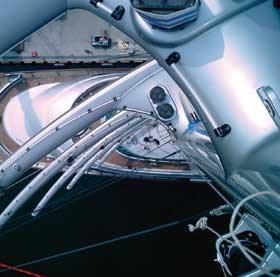
The carbon/epoxy masts — from bow to stern, the foremast, mainmast and mizzen mast — are approximately 57m/187 ft tall and each weighs about 26 tons/23,640 kg. In cross-section, each is circular at the heel, or base, to allow connection to large heel bearings in the rotation mechanism that turns the masts into the wind. Above deck, the circular profile changes to a more aerodynamic ellipse, which reduces drag. Using a maximum design wind speed of 60 knots/70 mph with all sails set and a safety factor of 1.8, the masts had to withstand bending loads of 18 million Nm or about 13.28 million lb/ft, which is approximately three times the load experi-enced by the largest wind turbine ever built, according to Insensys.
“The principal structural demand was the bending moment caused by the driving and drag forces through the sails at the mast attachment points,” explains Roberts. “These forces are highest at the deck bearing and diminish progressively up the rig, which permitted an aggressive taper from the deck upwards.” Roll, pitch and heave dynamic loads had to be considered as well.
The design was further complicated by the fact that the masts, sails and hull operate as a system. The boat would never make way with sails set only on the mizzen mast, for example, but rather with a combination of sails coordinated across all three masts. Therefore performance requirements for each mast had to be determined in relationship to the other two. Because the mainmast takes the heaviest wind loads, the design assumes less sail and lower wind loads for the foremast and mizzen. Therefore, it was necessary to customize the laminate design for each structure.
In addition to the three masts, Roberts’ team also was tasked with designing the vessel’s 18 yards (in three different sizes), which support the sails. The design also included 18 complexly curved “truss units” that attach the yards to the masts. “The truss units have quite a sophisticated internal shape to incorporate the winch and drive units for furling and unfurling the sails,” Roberts reports.
Modeling, testing and monitoring
“Empirically derived standards were not available for this design,” notes Roberts. “It was thus essential for us to carry out extensive modeling to minimize development risks.”
NISA finite element analysis (FEA) software, supplied by Cranes Software Inc. (Bangalore, India), was used to establish a global model so that an initial design could be completed. Material coupon testing established basic mechanical properties. The selected design for the masts called for hollow, tapered, monolithic (uncored) carbon/epoxy tubes, 1.1m/3.61 ft in diameter at the heel bearing, transitioning to a 1.8m/ 5.9 ft by 1.1m/3.6 ft ellipse just above the deck and then tapering to 600 mm/23.6 inches by 400 mm/15.8 inches at the tip. Each mast was fabricated in two halves and bonded together to form the tubular shape.
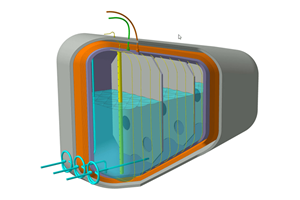
Modeling results dictated the addition of an H-shaped internal spar to prevent buckling. An issue was how to accommodate the self-furling sails — because the rolled-up sails are housed within the mast, a wide, open slot and sufficient interior space had to be designed into the structure. Roberts placed the open slot between two of the H-spar arms, an arrangement that maintains the mast’s bending stiffness; the design ensures that internal strengthening flanges inside the H-spar don’t compromise sail and rope storage.
Approximately 180 plies make up the mainmast laminate at the base, a number that declines to 20 plies at the tip, with drop-offs along the length to create the taper. Laminate thickness at the base is approximately 50 mm/2 inches. High-strength T800 intermediate-modulus carbon fiber, supplied by Toray Carbon Fibers (Tokyo, Japan), was specified for the vertical (0°) axis and for +/-45° plies for strength and stiffness. Dry unidirectional tapes were wet out on site with an impregnator to control fiber/resin ratio. Notes Roberts, “This is a relatively thin-walled structural design, given the ratio of wall thickness to the total part diameter.”
To validate the design and monitor structural loads during sailing, Insensys designed and supplied a fiber-optic load-sensing system for both masts and yards. The system uses an opto-electronic interrogation unit (about the size of a book) coupled to a laptop computer. It measures strain by passing light pulses through multiple 0.25 mm/0.01 inch-diameter fiber-optic cables that are integrated into the laminate during fabrication. The cables run along the mast’s 0° axis, each at a different point on the mast’s circumference. At discrete points along the cables, small Bragg diffraction grating sensors have been created in the cable core by laser-marking the core with optical interference patterns. As the mast or yard and its embedded sensors are strained, extended or compressed, the sensor’s light transmission characteristics and, thus, the wavelength of the transmitted light change. The change in wavelength is directly proportional to the strain. A simple, easy-to-understand graphical interface displays the forces on the computer screen. “This system is particularly suitable to a marine application, given its very light weight, the ability to place multiple sensors on a single cable and the fact that it is unaffected by electromagnetic radiation or saltwater when embedded within the laminate,” explains Roberts.
A 1/6th-scale test mast section and spar were fabricated with embedded sensors to check the performance of the parts under bending loads and to confirm the model’s predictions. Wind tunnel and structural load tests showed the mast’s flexural modulus to be 86.2 GPa/9,862.6 ksi/12 million psi, with the H-section spar providing adequate stabilization. Wind tunnel tests on the test rig, equipped with a single sail, validated the furling mechanisms. The test rig and sail also were fitted into a small hull for actual field trials at the port of Amsterdam, reports Roberts.
Design confirmed in the real world
Building the masts and spars was an accomplishment in itself. To keep tooling costs as low as possible,
one mold set was used to hand lay all three masts — two open, female, carbon/epoxy tools (one for each mold half) were pulled from a traditional strip-plank wooden plug. Aluminum tool inserts accom-modated differences between the laminate thicknesses of the masts. The H-shaped spars were molded in a separate tool and then bonded to each mast’s inner surface. Fiber-optic cables were embedded close to the interior skin of the masts to keep them as far as possible from the marine environment. A long out-life epoxy supplied by Pro-Set Inc. (div. of Gougeon Brothers Inc., Bay City, Mich.) and woven T800 carbon fiber cloth were used to wet-laminate the bond line or joint between the mast halves after they were joined using Spabond epoxy adhesive from SP (part of Gurit, Isle of Wight, U.K.). The adhesively bonded
H-beam provided additional bonding surface to ensure integrity of the mast joint, says Roberts. Four different molds were employed to fabricate the curved yards, using a method similar to that for the masts, but without an H-spar. The substantial, curved carbon/epoxy truss units were vacuum infused, using preforms made of high-areal-weight woven carbon fabric.
After they were cured and painted, masts were “stepped” — lifted and set in place — with the aid of two 500-ton cranes. The masts sit on steel collars, which are held by steel heel bearings that are, in turn, driven by a massive hydraulic rotation mechanism below deck. In the cabin, the exposed mainmast is encircled by a dramatic spiral staircase, Roberts reports.
The completed $100 million (USD) vessel, built by Perini Navi (Viareggio, Italy) at its Turkish subsidiary shipyard Yildiz, already has sailed more than 10,000 miles, with more than 2,000 successful sail deployments, reports Roberts. Says owner Perkins, “The boat’s performance has satisfied our highest hopes and expectations.” The boat is available for charter through Perini Navi USA (www.symaltesefalcon.com).
Related Content
Polar Technology develops innovative solutions for hydrogen storage
Conformable “Hydrogen in a Box” prototype for compressed gas storage has been tested to 350 and 700 bar, liquid hydrogen storage is being evaluated.
Read MoreCollins Aerospace to lead COCOLIH2T project
Project for thermoplastic composite liquid hydrogen tanks aims for two demonstrators and TRL 4 by 2025.
Read MoreComposites end markets: Batteries and fuel cells (2024)
As the number of battery and fuel cell electric vehicles (EVs) grows, so do the opportunities for composites in battery enclosures and components for fuel cells.
Read MoreHonda begins production of 2025 CR-V e:FCEV with Type 4 hydrogen tanks in U.S.
Model includes new technologies produced at Performance Manufacturing Center (PMC) in Marysville, Ohio, which is part of Honda hydrogen business strategy that includes Class 8 trucks.
Read MoreRead Next
VIDEO: High-volume processing for fiberglass components
Cannon Ergos, a company specializing in high-ton presses and equipment for composites fabrication and plastics processing, displayed automotive and industrial components at CAMX 2024.
Read MorePlant tour: Daher Shap’in TechCenter and composites production plant, Saint-Aignan-de-Grandlieu, France
Co-located R&D and production advance OOA thermosets, thermoplastics, welding, recycling and digital technologies for faster processing and certification of lighter, more sustainable composites.
Read MoreAll-recycled, needle-punched nonwoven CFRP slashes carbon footprint of Formula 2 seat
Dallara and Tenowo collaborate to produce a race-ready Formula 2 seat using recycled carbon fiber, reducing CO2 emissions by 97.5% compared to virgin materials.
Read More


.jpg;maxWidth=300;quality=90)


