Pultruded Composites Span Infrastructure Gaps
Pre-engineered deck and superstructure systems are finding their niche in many locations around the world.
As was the case with structural steel a century ago, many civil engineers still consider composites as cutting-edge, nontraditional materials, to be approached with caution. Nevertheless, composites are continuing their steady advance into a wide variety of infrastructure projects. Since our last review of bridge activity, several more composite-intensive bridges have been installed for both vehicular and pedestrian service, around the globe.
Interestingly, no single approach has been universally accepted, in part, because of composites' design flexibility. Myriad approaches are vying for attention and market share, from composite-enhanced wood timber bridges to hand layed up beams to hybrids combining composites with traditional concrete. Bridge superstructures and decks made with pultruded profiles, however, are being installed more than any other, and some believe they are the composite bridge of the future. "Pultruded bridges work well, in my opinion, and several manufacturers have credible products," says Mark Henderson, head of the bridge design group at LJB Inc. (Dayton, Ohio), a well-known engineering firm. "At our company we're working toward pre-engineered deck systems that are designed and tested as a unit -- it's analogous to precast concrete parts that are designed and built offsite, such that you can drop them into place." This article takes a look at the most active practitioners in the field, although other manufacturers, such as Fiberline Composites A/S (Kolding, Denmark) and Strongwell (Bristol, Va.) also offer pultruded deck systems. Notably, Fiberline recently pultruded the first vehicular composite bridge on the European continent, in Klipphausen, Germany.
DECKS FOR DRAWBRIDGE DESIGNS
Martin Marietta Composites Inc. (MMC, Raleigh, N.C.) has installed more than two dozen of its patented and trademarked DuraSpan pultruded vehicular decks throughout the U.S. and abroad -- more than any other manufacturer. MMC focuses on decks, which are designed for placement over steel or concrete support girders. DuraSpan decks are made in standard 125 mm/5-inch or 192 mm/7.66-inch thicknesses to fit a variety of applications. Custom thicknesses and designs also are available.
The company's most recent project involved replacement of the deck on an historic drawbridge where U.S. Rte. 101 spans the Siuslaw River in western Oregon. The drawbridge is a double-leaf bascule -- meaning the bridge splits in the middle and the halves open to near-vertical position to allow ships to pass.
Originally fabricated in 1936 from wood, the deck was later replaced with open steel grating. The Oregon Department of Transportation (Oregon DOT) opted to replace the steel deck with composite material, for several reasons. First, the bridge carries 20,000 vehicles per day, so rapid replacement was required. The pre-made composite DuraSpan panels could be dropped in on one lane while the adjacent lane remained open to traffic. Second, Oregon DOT had specified a solid surface deck, rather than open grating, to provide weather protection for the underlying support beams, which would not be replaced. A composite solid surface deck was the only one that could meet the Oregon DOT's weight requirements. A third and very important reason in a location so near the Pacific Ocean was composites' resistance to corrosion. Finally, the DuraSpan 500 deck is equivalent in thickness to standard steel deck grating, so no retrofits or haunches would be required.
A DuraSpan deck consists of multiple copies of a basic 600-mm/24-inch wide pultruded profile, bonded together. Each MMC-engineered profile, which the company calls a dual-cavity beam, consists of four, hollow, trapezoid-shaped tubes formed by two near-vertical, angled inner walls, with thin extensions of the top and bottom surfaces on one edge for joining one profile to the next. Creative Pultrusions Inc. (Alum Bank, Pa.) pultrudes the parts for MMC under contract, using isopolyester resin supplied by Reichhold Inc. (Research Triangle Park, N.C.) and stitched triaxial and quadraxial fiberglass engineered fabrics from VectorPly (Phenix City, Ala.). Fiber orientation is "a balanced quasi-isotropic layup" says MMC's senior engineer Matt Sams. Unidirectional glass fiber is added in some applications for additional stiffness. "The goal has been to achieve enough stiffness to meet AASHTO [American Association of State Highway and Transportation Officials] deflection requirements, without using too much material," says Sams. "We're able to meet the requirements by optimizing fiber orientation." Full-scale fatigue and damage tolerance testing at several universities has proven the design's load-carrying ability, which easily meets AASHTO HS25 (45 tons).
MMC interlocks and bonds the profiles together in series to achieve the specified deck panel lengths for a job. For the Siuslaw drawbridge, panels were approximately 2.4m/8 ft wide and 4.3m/14 ft long, oriented so that the core tubes run perpendicular to the traffic direction. Thirty-six panels were required to cover both lanes over the bridge's 45.4m/149-ft span. MMC provided onsite support during installation.
The underlying steel support girders were riddled with old boltholes, reports Sams. MMC normally recommends that the contractor weld steel studs onto the girders, mate the studs to holes in the underside of the panels, and then fill the holes with high-strength grout. For this project, the pre-existing holes meant that stud placement would be a challenge. "Our options were limited," says Sams. "We had to adapt to the existing structure," In lieu of studs, blind rivet-type fasteners were shot through existing holes in the girders' top flanges into the underside of the panels to secure them.
On the deck's upper surface, a thin, steel "cap," essentially a weather-tight filler strip, was placed along the bridge centerline, where adjacent panels were butted and bonded together. A nominal 12.7-mm/0.5-inch thick, urethane-based overlay wear surface was applied to the top of the deck after installation.
This is not the first bascule bridge to receive a DuraSpan deck -- previous MMC installations include three other Oregon drawbridges (see CT July/Aug 2001, p. 10, for one). Although the DuraSpan deck presents a solid fiberglass surface, it weighs no more than the open steel grid it replaces, and it is much quieter, reports Oregon DOT's Ray Bottenburg: "The composite deck significantly reduces noise for nearby residents and office workers, compared to the steel grating, which made a loud ringing sound, particularly with truck traffic." Skid resistance also is better, for safer driving conditions.
A DROP-IN FROM DOWN UNDER
Wagners Composite Fibre Technologies Manufacturing (WCFTM, Toowoomba, Queensland, Australia) is marketing a complete drop-in bridge -- deck and support girders -- in a superstructure design that combines pultruded composites and concrete. Since it successfully installed a vehicular bridge of this type in Queensland, Australia, the company has put a U.S. example in place, on New Oregon Rd. in Erie County, N.Y. The bridge owner is the Erie County Department of Public Works (Buffalo, N.Y.).
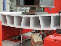
Originally designed and tested in conjunction with the University of Southern Queensland, Wagners' hybrid bridge system design has been refined to simplify and accelerate installation as much as possible, says Neil Wagner, managing director. The design is intended to provide the high performance of composites with fast assembly of very simple modular components. A superstructure "panel" is made with 100-mm/4-inch-square pultruded fiberglass profiles, stacked on top of each other to a height dictated by the project deck thickness and overall bridge span -- more profiles, stacked higher, mean greater strength and stiffness. The stacked profiles are bonded to each other and to a flat pultruded bottom plate, using a toughened epoxy. The stacks of square profiles form the webs and the flat plate acts as the bottom flange of a simple box beam. The spacing of the bonded stacks is determined by the particular project.
A panel is completed with a top wear surface of high-strength concrete about 150 mm/6 inches thick, poured at Wagners' Australian facility. (An inexpensive, lightweight, non-load-bearing wood panel keeps the concrete from penetrating the space between the webs during cure.) The concrete is designed to work "compositively" with the FRP elements, that is, the concrete, the pultruded webs and the bottom flange work together to handle the imposed loads. While Wagners normally does not use steel reinforcing bar or grid in its concrete, a stainless steel grid was placed in the concrete for the Erie County bridge to reduce shrinkage and better combat wintry conditions and road salt.
Wagner explains that the design is a simple modular concept founded on basic engineering principles. "Concrete is good in compression, the pultruded profiles have fiber architecture that's good in shear, and the bottom flange is designed for tension," he explains. "The number of webs, their spacing, the thickness of the bottom flange are all engineered to fit the span length and bridge width -- it's like a snap-together system."
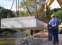
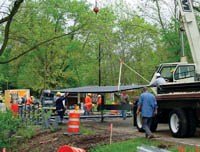
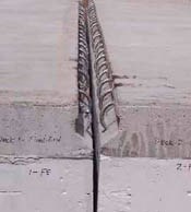
Panels for the Erie County bridge were designed with five webs, with a resulting width of 2m/7 ft, and were 9.4m/30.5 ft long, spanning the creek. A total of four panels were required for the job. The bridge's short span meant that each 11-metric-tonne/24,000-lb panel could be picked and placed with an excavator rather than a crane. Existing bridge abutments had been demolished and rebuilt with precast concrete blocks, atop cast-in-place concrete footings doweled to bedrock. Adjacent panels were bonded together with epoxy and "shear keys," which are steel rebar loops embedded in coved recesses that run the length of the top edges of the concrete wear surface (see photo, p. 31). The shear keys are wired together with more rebar and then the recess between mated panels is filled with high-early-strength grout. Holes in the bottom flange fit over four steel rods on each abutment, which act as anchor bolts to tie the panels to the concrete substructure. Standard steel bridge railings, consistent with New York State Department of Transportation (NYSDOT) standards for low-volume roads, were through-bolted to the outer panel edges -- two bolts in the concrete section and two bolts in the composite web, for a total of four bolts for each vertical railing post.
"We design each bridge cross-section based on transformed section analysis, a common structural engineering tool used for reinforced concrete beam design," says Wagner. "We believe this tool can be used reliably for composite structures as well. The results of hand calculations, finite element analyses, full-scale moment tests and fatigue tests are within 5 to 10 percent of each other." Live load testing confirmed the calculations, says Jonathan DePlanche, project engineer for TVGA Consultants (Elma, N.Y.), who reviewed and certified Wagners' design for use in New York. Two fully loaded dump trucks drove over the instrumented span to determine the actual strains and deflections of the in-service bridge. Bridge Diagnostics Inc. (BDI, Boulder, Colo.) provided the strain gauges and set up the live load test. Designed to an AASHTO HS25 rating (41 metric tonnes/90,000 lb), the bridge easily supports approximately 243 metric tonnes/534,000 lb, says DePlanche. "The neutral axis is right where it's supposed to be," he adds. "The concrete is in compression and the FRP is in tension. It takes good advantage of the different material properties."
Carl Dimmig, Erie County's bridge manager, is impressed with the Wagners bridge: "It's a very good product -- the initial cost is, of course, higher than a traditional bridge, but the lifecycle cost will be cheaper in the long run. We were able to install this bridge in 30 days, including the abutment work, as compared to three months for a traditional steel-and-concrete bridge."
MORE DECKS ON DECK
Bedford Reinforced Plastics Inc.'s (Bedford, Pa.) pultruded decks have been successfully installed in a number of locations, including the Clayton Rd. bridge, in Montgomery County, Ohio. Bedford pultrudes two standard deck profile designs, with different geometries: Prodeck 4 is a straightforward 600-mm/2-ft-wide, 100 mm/4-inch thick box beam profile with two inner vertical webs that, with the beam sides, form three hollow tubes. Female flanges on one side and male flanges on the opposite side make it easy to interlock and join adjacent profiles to form deck panels. The Prodeck 8 profile, 200 mm/8-inches thick, also is made with edge flanges, and has a beefier angle design that creates triangular-shaped hollow tubes. Bedford makes its profiles primarily with Knytex multiaxial "technical fabrics" from Owens Corning (OC, Toledo, Ohio) and a custom-formulated vinyl ester resin supplied by Ashland Specialty Chemical - Composite Polymers (Columbus, Ohio). Continuous strand mat and roving also are incorporated, supplied by either OC or Saint-Gobain Vetrotex (Valley Forge, Pa.). Rovings are oriented longitudinally (0*), parallel with the webs, for extra stiffness. Total fiber volume is approximately 70 percent by weight.
Montgomery County's current elected county engineer has committed to replacing at least one conventional bridge deck each construction season with a composite version, reports Tom Wright, Bedford's bridge market manager. Bedford was the low bidder on the Clayton Rd. composites project, and completed the bridge earlier this year with a Prodeck 4 deck. Profiles were pultruded in lengths to match the bridge's curb-to-curb width of 8.8m/28.5 ft. Four profiles were bonded together with Ashland's Pliogrip 8000 urethane adhesive to form a 2.5m/8-ft long panel. Five panels were needed for the bridge's 10.8m/35-ft single span.
Panels are supported on the existing steel I-beam stringers, spaced 1.2m/4 ft apart. Bent steel brackets, which Wright terms "Z-clamps," bolt to the underside of the panels and slide underneath the top flange of each stringer. Elastomeric bearing pads placed between the deck and the stringer ensure a tight fit. Because of the thin deck, no special wear surface is required; crews simply added 76.2 mm/3 inches of standard asphalt, continuous with the road approaches, Wright explains. "The entire deck took less than a day to install," he adds. "Rapid installation is the key for these engineers, since traffic detours and public inconvenience can be minimized."
Prodeck profiles have been extensively tested in long-term fatigue and failure scenarios at West Virginia University's Constructed Facilities Center. According to Wright, live load testing of the Montgomery County bridge likely will occur later this year. Meanwhile, Bedford has its eye on some potential large-scale bridge projects, and is investigating the use of the Prodeck 4, turned on edge, as a girder replacement. "Pultruded decks will be the future because of cost-effective, automated processing that produces repeatable and strong shapes," says Wright.
TOWARD A "SYSTEMS" APPROACH
While offsite manufacture of bridge components and rapid installation are cornerstones of composite bridge appeal, LJB's Henderson stresses that, to ensure a technology's wide acceptance and growth, composite bridge manufacturers must adopt a "total delivery system" approach. That includes not only the physical bridge parts but also design plans, bidding documents, liability for connections, prebid support and technical personnel in the field, which he considers a must for a successful composite bridge project of any type. "Composites have certainly worked for bridges, and have taken the game up to a higher level, positively impacting both cost and performance," he concludes. "I have no doubt composites will become a big part of structural designs -- the question is when." Erie County's Dimmig agrees: "We need to start bringing these composite technologies developed for other industries into civil engineering. In the long run, they can stand up to the extremes, like temperature and road salt, better than concrete and steel."
PROVING DURABILITY OF BRIDGE BEAM REPAIRS
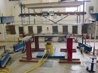
Composite materials are not only good materials for bridge superstructures, they also are being used more and more for bridge repair. Investigators are working to test the long-term durability of externally bonded FRP materials for concrete rehabilitation. Among them is Dr. Trey Hamilton, associate professor at the University of Florida's department of civil and coastal engineering. He and two other Florida researchers won the best technical paper award at the 2004 American Composites Manufacturers Assn. (ACMA) convention, with a discussion of the performance of corrosion-damaged beams that were repaired with unidirectional carbon fiber material wet out with epoxy. In the study, steel-reinforced concrete beams were subjected to flexural loading until cracks were propagated. The effects of long-term corrosion were simulated by saturating cracks with a concentrated salt solution and applying a weak electrical current. Severely corroded areas were then cut out, and the beam was repaired with concrete patches and strengthened with carbon/epoxy sheets. Further load testing and corrosion cycles showed that the FRP-strengthened beams had higher load capacity than an untouched control beam, particularly the beams that were repaired using a single-wrap scheme, in which a continuous carbon ply covered the sides and bottom of the beam. Measured load capacity for beams with the continuous wrap increased up to 32 percent compared to the control, after two corrosion cycles. Further, says Hamilton, the wrap helped slow corrosion by reducing the diffusion of chlorides into the concrete. "Our tests show that beam stiffness can be regained by FRP application," he says.
Related Content
KU researchers explore FRP materials for dams, levee reinforcement
To address aging infrastructure, a team of researchers at KU is conducting research into repairing and retrofitting 700-plus dams, levees and related structures nationwide using FRP materials.
Read MoreCirculinQ: Glass fiber, recycled plastic turn paving into climate solutions
Durable, modular paving system from recycled composite filters, collects, infiltrates stormwater to reduce flooding and recharge local aquifers.
Read MoreComposites end markets: Infrastructure and construction (2024)
Composites are increasingly used in applications like building facades, bridges, utility poles, wastewater treatment pipes, repair solutions and more.
Read MoreSGL Carbon carbon fiber enables German road bridge milestone
A 64-meter road bridge installed with carbon fiber reinforcement is said to feature a first in modern European bridge construction, in addition to reducing construction costs and CO2 emissions.
Read MoreRead Next
VIDEO: High-volume processing for fiberglass components
Cannon Ergos, a company specializing in high-ton presses and equipment for composites fabrication and plastics processing, displayed automotive and industrial components at CAMX 2024.
Read More“Structured air” TPS safeguards composite structures
Powered by an 85% air/15% pure polyimide aerogel, Blueshift’s novel material system protects structures during transient thermal events from -200°C to beyond 2400°C for rockets, battery boxes and more.
Read MorePlant tour: Daher Shap’in TechCenter and composites production plant, Saint-Aignan-de-Grandlieu, France
Co-located R&D and production advance OOA thermosets, thermoplastics, welding, recycling and digital technologies for faster processing and certification of lighter, more sustainable composites.
Read More






.jpg;maxWidth=300;quality=90)


