
Testing Tech: Shear testing of sandwich panel core materials
In my previous column (HPC November 2006, p. 10), I noted that the shear strength and shear stiffness of the core material in a sandwich panel can be determined in situ while performing flexural tests to evaluate other sandwich panel properties. However, as was stated then, it is more accurate to measure these


Source: Don Adams
In my previous column, I noted that the shear strength and shear stiffness of the core material in a sandwich panel can be determined in situ while performing flexural tests to evaluate other sandwich panel properties. However, as was stated then, it is more accurate to measure these properties by a direct test method, such as the one that follows.
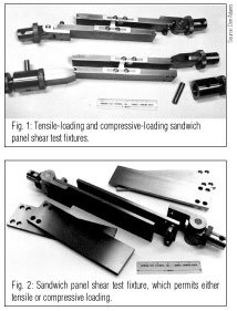
The core material, either by itself or already combined with facesheets, is adhesively bonded to stiff plates and then subjected to a shear loading essentially parallel to the plane of the plates. This shear loading may be obtained by applying either a tensile or a compressive force to the bonded assembly. ASTM C 394, "Standard test Method for Shear Fatigue of Sandwich Core Materials,"permits the use of either method. In Fig. 1, the fixture at top is set up to apply tensile loading while the one below it applies a compressive loading. In this case, each bonding plate has a notch at one end for compressive loading and tensile loading attachment holes at the other end, permitting the same plates to be used in both loading modes. This increases fixture cost, however; since most laboratories tend to use one loading mode or the other exclusively, this dual-use construction is unnecessary. Note also that the particular fixtures shown in Fig. 1 include adjustable brackets mounted on the plate edges for attachment of an extensometer to measure shear strain and hence calculate core shear modulus, if desired.


Fig. 2 shows a simpler fixture configuration that is more commonly used today. It emphasizes the application of tensile forces to induce the desired shear loading, although compressive forces can be applied instead, if desired. The resulting shear stress state is the same for both modes of force application, but tensile loading is usually preferred because buckling of the relatively long load train then is not a concern. In fact, the bonding plates shown in Fig. 1 are thicker than those in Fig. 2, to help prevent buckling.
Actually, thick plates are technically desirable, not only to resist buckling, but for bending resistance as well. When the plates are loaded, either lateral (out-of-plane) forces or bending moments, or a combination of the two, are induced at their loaded ends. Thus, a thick, stiff material is desired for the bonding plates. Steel is the economical choice, but thick steel plates are heavy and, thus, cumbersome during bonding and fixture installation operations. For this reason, a trade-off is usually made between plate rigidity and weight. This is recognized in ASTM C 394, which states, "The thickness of the plates may be varied in accordance with the strength of the sandwich...."That is, it permits the use of thinner plates for low-shear-strength core materials, for which the applied forces required to achieve failure are relatively low.
Because of the induced lateral forces and/or bending moments at the ends of the plates, and because the ends of the test specimen itself are free surfaces (making the shear stress zero there), local stress disturbances occur at the specimen ends. But as the distance from these free ends increases, the shear stress becomes more uniformly pure shear. Thus, a specimen that is long relative to its thickness is used to reduce the influence of the local stress concentrations in the mid-length of the specimen where shear modulus is to be determined. Experimental and analytical studies - the first dating back to the early 1900s - have suggested a specimen length-to-thickness ratio of 12:1; therefore, this is the minimum ratio specified in ASTM C 273. However, the measured shear strength can be influenced by the stress concentrations that occur anywhere, including at the free ends, independent of specimen length. Thus, shorter specimens can be used if, as is often the case, only core shear strength is being determined. However, ASTM C 273 does not sanction this; it permits longer but not shorter specimens.
At one time the specimen definition in ASTM C 273 required a minimum specimen width not less than twice the core thickness, but at present it is simply specifies a minimum width of 50 mm/2 inches. The fixtures shown in Figs. 1 and 2 have 76-mm/3.0-inch wide bonding plates.
Another issue is the line of action along which the loading (whether tension or compression) is to be applied. ASTM C 273, first published in 1951, has always specified that the load line is to pass through the diagonal corners of the specimen, as in Fig. 1. On the other hand, intuition would suggest that to achieve a shear loading, the loads should be applied parallel to the facesheets. Various studies, both analytical and experimental, have indicated that the load line location doesn't make a significant difference. Diagonal loading induces an undesirable bending moment at each end of the specimen, but parallel loading induces an equally undesirable lateral force at each end. And both load lines result in similar stress concentrations and distributions at the specimen ends. See O'Conner1 and Garcia, et. al.2 for more details and additional references.
These loading requirements are significant because the test fixture is typically designed for a specific core shear specimen length and thickness. (ASTM C 273 does not specify specimen thickness, only length-to-thickness ratio.) For diagonal loading, if the thickness is altered, the specimen length must be changed correspondingly if the desired diagonal-through-the-corners line of action is to be maintained. For parallel loading, the force application point in the end fittings must be adjustable so that the loading still can be applied through the mid-plane of the specimen as thickness is altered.
Thus, if it is accepted that some freedom in load line application can be permitted without influencing the test results, testing and test fixturing can be significantly simplified.
Finally, it should be noted that, whatever loading configuration is used, the bonding plates themselves are relatively expensive to fabricate and would not, therefore, normally be considered disposable. Thus, a secondary concern is the cleaning of the plates after each test. After manual removal of as much of the failed specimen and adhesive as is practical (labor also is expensive), final clean-up in preparation for the next series of tests can be done by burn-off, chemical dissolution or grinding. While the latter is common, burn-off also can be effective. The required temperature obviously depends on the adhesive used and the type of plate material. A temperature in the range of 425°C to 575°C (about 800°F to 1070°F) is typical. For example, ASTM D 3171, in discussing methods of determining fiber and void volume contents of composites, suggests a burn-off temperature of 565°C, ±30°C (1050°F, ±54°F). This same standard also specifies multiple procedures for chemical dissolution. One must keep in mind, however, that the polymer adhesive is to be dissolved, not the plate. Plate life can be extended if, by proper design, both surfaces can be used, as is the case with those plates shown in Figs. 1 and 2.
References 1^ D.J. O'Conner, "A Comparison of Test Methods for Shear Properties of the Cores of Sandwich Constructions,"Journal of Testing and Evaluation, Vol. 17, No. 4, July 1989, pp. 241-246.
2^ R. Garcia, T.A. Weisshaar, and R.R. McWithey, "An Experimental and Analytical Investigation of the Rail Shear Test Method as Applied to Composite Materials,"SESA Paper No. R79-105, Proceedings of the 1979 SESA Spring Meeting, San Francisco, Calif., May 1979, Society of Experimental Stress Analysis (now, Society of Experimental Mechanics, SEM).


.jpg;maxWidth=300;quality=90;format=webp)


Related Content

Multi-scale 3D CT imaging enables digital twinning, high-fidelity simulation of composite structures
Computed tomography (CT) provides highly accurate 3D analysis of internal microstructure, performance simulation of carbon fiber/PEEK satellite strut.
Read More
Testing to support composite bolted joint analysis
An overview of ASTM Standard Guide D8509, and its coupon-level mechanical testing of design properties for analyzing composite bolted joints.
Read More
Composite test methods (and specifications) for fiber-reinforced concrete structures
While initially focused on transitioning existing standards published by the American Concrete Institute, the relatively new ASTM Subcommittee D30.10 is developing new standardized test methods and material specifications for FRP composites.
Read More
Notched testing of sandwich composites: The sandwich open-hole flexure test
A second new test method has been standardized by ASTM for determining notch sensitivity of sandwich composites.
Read MoreRead Next

“Structured air” TPS safeguards composite structures
Powered by an 85% air/15% pure polyimide aerogel, Blueshift’s novel material system protects structures during transient thermal events from -200°C to beyond 2400°C for rockets, battery boxes and more.
Read More
Plant tour: Daher Shap’in TechCenter and composites production plant, Saint-Aignan-de-Grandlieu, France
Co-located R&D and production advance OOA thermosets, thermoplastics, welding, recycling and digital technologies for faster processing and certification of lighter, more sustainable composites.
Read More
Developing bonded composite repair for ships, offshore units
Bureau Veritas and industry partners issue guidelines and pave the way for certification via StrengthBond Offshore project.
Read More