Multi-scale 3D CT imaging enables digital twinning, high-fidelity simulation of composite structures
Computed tomography (CT) provides highly accurate 3D analysis of internal microstructure, performance simulation of carbon fiber/PEEK satellite strut.
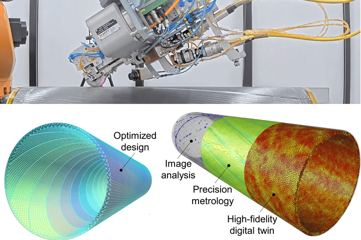
Shown here is the laser tape placement process for manufacturing dimensionally stable structures (top), a carbon fiber-reinforced-polyetheretherketone (PEEK) thermoplastic composite satellite strut designed and optimized for low coefficient of moisture expansion (bottom left) and CT imaging of the strut used for void segmentation, metrology and creation of a digital twin for high-fidelity performance simulation (bottom right). Photo Credit, all images: New Frontier Technologies Pty Ltd.
With the increasing adoption of fiber-reinforced composites, the capability to investigate and characterize parts in 3D is crucial. This is particularly important for high-performance applications where loading conditions can be extreme and demand absolute assurance of performance. The complex internal microstructure of composites underscores the need for 3D analysis, essential for detailed quality assessment and the generation of digital twins for high-fidelity performance simulation. Traditional nondestructive visual or surface diagnostic methods fall short in providing the necessary in-depth structural data analysis of a part. Instead, computed tomography (CT) can provide a basis for highly accurate 3D structural inspection and performance evaluation in applications for space, aerospace, automotive and new growth industries such as energy storage.
Using recent advances in scanning hardware, image reconstruction algorithms, high-performance computing and image analysis software (including AI-based techniques), unprecedented insight into the microstructure and internal geometry of composites can be provided. CT scans can be analyzed to extract properties and to create digital twins where individual properties including voids and other defects, fiber and metrology information, are applied to volumetric meshes. These digital twins enable accurate, high-fidelity finite element simulation for performance prediction. Importantly, characterization and modeling can be applied at both the input (raw material analysis) and output (completed parts and structures) stages of the manufacturing process.
However, analysis and modeling of composite CT scans is not always straightforward. New Frontier Technologies (NFT, Canberra, Australia) has decades of combined research and technology expertise in the application of CT scanning and 3D imaging analysis to turn deep interior inspection of materials and parts into decision, simulation, modeling and certification tools. NFT has recently completed work on a space case study that demonstrates the value of CT-based 3D analysis of composites.
Case study: CF/PEEK satellite strut
Sectors such as space have demanding performance requirements that can only be achieved with state-of-the-art design and manufacturing of the part. Space instrumentation requires dimensionally stable structures under the extreme thermal cycling of a space environment. Using automated fiber placement (AFP) with carbon fiber-reinforced polymer (CFRP) composites, zero coefficient of moisture (CME) and thermal expansion (CTE) can be achieved through careful design of tape/tow orientation.
A case study example involves a 500-millimeter-long satellite strut with a 55-millimeter internal diameter. This zero-CME structure was manufactured using carbon fiber-reinforced polyetheretherketone (CF/PEEK) tape and laser-assisted tape winding (LATW). It was then investigated by CT.
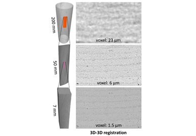
Figure 1. Multi-scale imaging of CF/PEEK satellite strut. Analysis at different resolutions — voxel size 23, 6 and 1.5 µm — shows tape layup 3D architecture and accurate mapping of the plies.
With CT imaging, the scanning resolution is set by geometrical magnification — in rough terms, the larger the part to be scanned, the lower the resolution. For the satellite strut, the 3D image of the overall part, despite being lower resolution, still provides detailed information for metrology and identification and quantification of structural defects.
However, for manufacturing optimization and high-fidelity simulation, higher resolution scanning is desirable. This was achieved by employing a multi-scale imaging workflow where scans were completed and then 3D-3D registered to make each set geometrically spatially aligned. Analysis of the images at different resolutions — voxel size 23, 6 and 1.5 µm (Fig. 1) — allowed detailed inspection of the tape layup 3D architecture and accurate mapping of the layers placed at different angles.
Multi-scale CT imaging, simulation
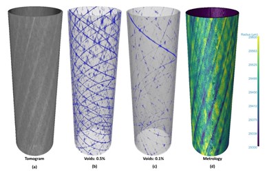
Multi-scale CT scanning is very powerful for identifying structural defects, even those that are very small and below the surface. In an earlier prototype of the satellite strut, gaps between tapes were inspected and digitally isolated. These voids could be matched to the process data to identify which layers they occurred on. Moreover, their width could be measured. This information was fed back to the manufacturing process, achieving precise adjustment of the design and laser AFP process parameters, resulting in the virtual elimination of large gaps (<0.1% volume) in the subsequent iteration (Fig. 2).
Figure 2. The revised satellite strut. (a) CT image of the revised strut, (b) images showing void distribution and content of the earlier prototype, (c) the revised prototype after optimization of manufacture and (d) metrology of the revised tube.
The use of real 3D geometries provides significant value by informing accurate high-fidelity models and simulations. Manufactured parts and their internal microstructure can vary substantially from idealized and theoretical designs. This variance can cause meaningful differences in properties, such as stiffness, strength, failure behavior and lifetime durability.
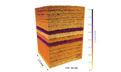
Figure 3. High-resolution scanning. Fiber orientation and fiber volume fraction (FVF) analysis from high-resolution CT scan.
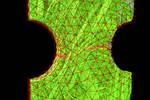
Multi-scale imaging also enables high-fidelity simulation of large structures with high-resolution scans used to obtain material properties of the manufactured part. Using the highest resolution image acquired on the satellite strut, the orientation of individual fibers was mapped, and the fiber volume fraction (FVF) accurately calculated for each layer and averaged over the tube thickness (Fig. 3).
FEA simulation results
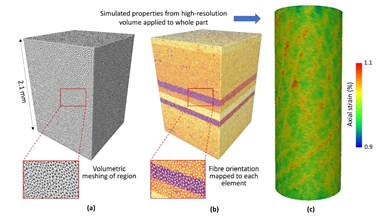
Figure 4. Multi-scale simulation of satellite strut. (a) Volumetric mesh, (b) high-resolution simulation including mapping of fiber orientation and (c) simulation of the whole part.
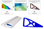
Several representative high-resolution regions were digitally extracted and volumetrically meshed for finite element simulation (Fig. 4). For these regions, information derived from previous image analysis, such as fiber orientation and phase volume fraction, was locally mapped to each element (Fig. 4b). These volumes were used to simulate the moisture and thermal expansion properties along with mechanical characteristics. The simulated properties were then applied to the whole structure to model its performance under demanding mechanical and environmental conditions. The adaptability of this multi-scale approach means that digital material twins can be created for virtually any composite part.
Although CT imaging is increasingly used for composite materials and structures, an accurate characterization of the material properties may pose challenges. NFT can assist with advanced analysis of any CT scan of composites for part design, diagnostic or failure investigations. As high-fidelity digital twins are more broadly used, the importance of 3D knowledge of the internal structure is becoming apparent. Similarly, NFT can provide detailed geometrical and microstructural analysis to enable composite material refinement and design optimization to meet stringent quality and performance requirements.
About the Author
Dr. Paul Compston
Dr. Paul Compston is CEO and director of New Frontier Technologies Pty Ltd. (Canberra, Australia) He has more than 20 years of experience as an industry-focused researcher in advanced manufacturing and characterization of composite structures for space, aerospace, automotive and other high-performance sectors. He leads the company in the development of innovative composite structures and digital manufacturing techniques for high-value applications. Compston is an Honorary Professor in the ANU Research School of Physics and a Fellow of the Institution of Engineers Australia.
Dr. Silvano Sommacal
Dr. Silvano Sommacal is the technical lead of the Advanced Diagnostics Division at New Frontier Technologies Pty Ltd. He is a material scientist with more than15 years of experience in 2D and 3D image acquisition, processing and analysis techniques gained while working in academia and industry. He holds a PhD from the Australian National University (ANU) and a master’s degree from the University of Padua (Italy).
Dr. John Holmes
Dr. John Holmes is a senior engineer at New Frontier Technologies Pty Ltd. with experience in characterizing, modeling and simulating composite materials. He has published in leading composite journals on testing, damage development, full-field characterization and finite element simulation of fiber-reinforced composites. He holds a mechanical engineering PhD in composite materials from the Australian National University (ANU) and is a visiting researcher at the ANU Research School of Physics.
Related Content
Measuring ply-wise deformation during consolidation using embedded sensors
Strip-type shape sensor method claims real-time measurement of ply-wise deformation.
Read MoreCrashworthiness testing of composites: A building block approach, Part 1
Determining the crashworthiness of composite structures requires several levels of testing and analysis, starting with coupon-level crush testing.
Read MoreCrashworthiness testing of composites: A building block approach, Part 2
Following the previously discussed coupon-level testing element, subcomponent and component testing are the next steps in designing crashworthy composite structures.
Read MoreDamage tolerance testing of sandwich composites: The sandwich flexure-after-impact (FAI) test
A second new ASTM-standardized test method assesses the damage tolerance of sandwich composites under flexural loading.
Read MoreRead Next
Improving carbon fiber SMC simulation for aerospace parts
Simutence and Engenuity demonstrate a virtual process chain enabling evaluation of process-induced fiber orientations for improved structural simulation and failure load prediction of a composite wing rib.
Read MorePart 2: Applying CT scan data analysis and visualization to composites
Advanced CT-scan analyses can offer deep insight into challenges faced when examining novel composites and hybrid material behavior or performing quality and certification testing. Part two of a two-part series.
Read MoreNondestructive inspection methods available to composites manufacturers
An overview of composite laminate inspection techniques ranging from manual testing methods to more advanced, noncontact options.
Read More
