Ukrainian Aerospace Developer Employs Clean Sheet Design
Antonov designs integral torsion boxes for highly loaded tail structures.
Carbon fiber composites have played a key role in commercial and military aviation progress — a true statement wherever aircraft are built. In the case of the Antonov Aeronautical Scientific/Technical Complex located in Kiev, Ukraine, composites have been incorporated into aircraft designs since the early 1970s. Founded in 1946 by aircraft pioneer Oleg Antonov and headed today by general designer Piotr Balabuyev, the Antonov "design bureau" is a well-known developer of a line of durable transport planes, both turboprop and jet versions. All are high-wing designs (with the exception of the AN-2 biplane) for ease of loading, landing on unpaved runways and other operating benefits. Over the company's history, a large number of its aircraft designs have been manufactured, including the AN-225 six-engined jet transport — the largest aircraft on record, built to carry the Soviet Union's version of the Space Shuttle.
A team of Antonov engineers initially began designing and manufacturing composite components to replace noncritical metallic parts such as doors, trim tabs and panels, but in the few years that followed, comparative performance tests convinced the company that composites could meet design specifications, so they were put into production. In 1975, the AN-72 model carried approximately 980 kg/2,156 lb of fiber-reinforced polymer in the belly fairing, engine nacelles, radome and other areas. The AN-124 super heavyweight model, the world's largest series production aircraft, incorporated composite parts throughout the airframe for a total of 5,500 kg/12,100 lb.
"The experience accumulated during the first stage opened the way for the transfer from low-stressed and medium-stressed composite structural components to highly loaded structures," says Victor Kazurov, deputy general designer.
Not black aluminum
In the late 1980s, design work began on the AN-70 transport model. General designer Balabuyev made the decision to develop composite torsion boxes for the tail structure. According to Vladimir Tsarikovsky, team leader of composite structures design, an analysis of composite designs used by other aircraft OEMs for highly loaded structures demonstrated that all showed, to some degree, the influence of more traditional metallic designs. Antonov designers wanted a "clean sheet," or a completely new design concept to fully exploit the unique properties of composites, while eliminating stress concentrators, minimizing the potential for impact damage and making production as straightforward and automated as possible. Their concept was an "integral" torsion box structure for the vertical and horizontal stabilizers.
"We reduced the number of parts to be joined, and rejected, to the extent possible, the use of mechanical fasteners to eliminate stress concentrator sources that composites are so highly sensitive to," says Tsarikovsky. "Load-carrying structures created by nature are always integral, without discrete joint points."
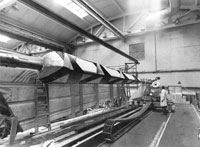
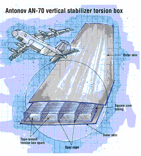
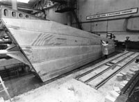
The design for the 10m/32.5-ft high vertical stabilizer and the two 7m/22.75-ft long horizontal stabilizer torsion boxes essentially involves tape-wound, hollow rectangular spar sections with spar caps (five in the vertical stabilizer and four in the horizontal stabilizer), molded with each other and covered with a core and outer skins to form a sandwich. The walls of the hollow spars and the outer sandwich skins, loaded primarily in shear, are designed with a high percentage of ±45° fibers. The unconventional sandwich core consists not of honeycomb, but 15-mm/0.6-inch-square continuous carbon fiber prepreg tubing — wound with ±45° prepreg tape — bonded to the spars and oriented chord-wise (i.e., parallel to the air flow, or front to back). Spar caps are made mainly with unidirectional prepreg tape. Root and tip ends of the spar caps are reinforced and the parts are attached to the fuselage with metallic fittings at a flange joint.
Pavel Gorobets, team leader for structural strength analysis, explains that the deformation of the integral structure under load differs considerably from the deformation of a traditional ribbed and riveted structure, which required a new approach for stress and strain analysis. Analytical tools and an in-house software program were developed to allow accurate strain analysis and optimum use of the composite material for this unusual design.
"A major challenge for developing the composite torsion boxes was design for manufacture," says Vasily Bondar, chief specialist for composite structures production. "Automation was obviously preferred, given the size of the parts as well as their critical structural function," he stresses. Antonov obtained a tape winder, developed by PROGRESS Production Assoc. (Savelovo, Russia), capable of winding parts as large as 2.5m/8.1 ft in diameter and up to 12m/39 ft in length.
Tooling represented another hurdle. A matched set of tapered rectangular winding mandrels for the spars was designed from fiberglass, based on the similarity of its linear coefficient of thermal expansion (CTE) characteristics with the CTE characteristics of carbon. One kit of five mandrels was fabricated for the vertical stabilizer, and a second kit of four mandrels was made for the horizontal stabilizer. For the small, square tubing used as core, a cable braider was used to wind prepreg tape over long, hollow mandrels made with extruded PVC and silicon rubber.
Selected materials included unidirectional carbon fiber/epoxy prepreg tape, 0.08 mm/0.003-inch thick and 10-mm/0.4-inch or 20-mm/0.8-inch wide, used for the skins, spar webs and the tubular cores. Thicker 0.24-mm/0.009-inch (240 to 265 gm/m2) carbon/epoxy tapes were used for the spar caps. The 130°C-/265°F-cure epoxy was selected for its long out-time (three to four months). The ARGON facility (Balakovo, Russia) was the material supplier. All materials were certified by the All-Russian Aviation Materials Research Institute (VIAM, Moscow, Russia).
The manufacturing sequence consisted of fabricating the flat stock for the spar caps, using the thick prepregs, then installing the caps on the winding mandrels and winding the hollow rectangular spar sections in sequence. The spar sections were then assembled in a fixture, vacuum bagged and cured as a single part in the first of two autoclave cure cycles.
Meanwhile, the small tubing was wound over the long PVC/silicone rubber mandrels in lengths approaching 150m to 200m/487 ft to 650 ft. The long tubing was wound over the cured spar structure while it rotated. The outer skin was molded separately, then placed over the part and the tubes, vacuumed bagged and cured in a second cure cycle. After cool down, the tapered spar section mandrels were removed and the part was trimmed. Leading edge and trailing edge carbon fiber profiles were then bonded onto the structure. After each manufacturing step, material integrity was checked using nondestructive test methods. In an innovative twist, the designers conducted specific destructive testing of coupons cut from the trim areas or coupons co-cured with the part.
The integral design offers substantial benefits, says Gorobets. The walls of the spars together with the spar caps carry most of the torque and bending moments. In contrast, the outer skin only has to resist air pressure loads. Since the outer skin is stressed so much less, any in-service damage it sustains doesn't affect structural performance of the part — it basically serves to protect the inner structure. Another benefit is that the core tubes allow any accumulated moisture to drain out of the part, in case the skin is not completely tight or it becomes damaged in service.
Future military transport
"Approximately 50 percent of the part material by weight is placed using automated methods," notes Kazurov. "If we incorporated machine-assisted hand layup, we could increase that to 70 percent." He also points out that the composite torque boxes weigh 30 percent less than metallic versions.
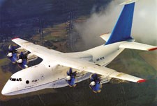
The prototype AN-70 was completed in early 1994 with 6,700 kg/14,740 lb of composites. Flight testing, initiated in late 1994, proved the plane's agility and short takeoff and landing (STOL) characteristics. However, the program was severely tested when on the fourth test flight, an observer chase plane collided with the prototype in midair, tearing off the tail structure. The prototype crashed, killing its crew. Remarkably, the program survived and a second prototype made its first flight in 1996. It has undergone extensive flight testing since then. The fly-by-wire AN-70 also incorporates other composite components, including the unique counter-rotating Russian Stupino 14-blade propellers with a reported 90 percent efficiency, landing gear doors, wing high-lift devices and others. Maximum payload capacity is 47 metric tonnes/103,160 lb.
Antonov engineers are of the opinion that over the course of the prototype production and testing, areas were identified for improvement in the design, as well as ways to shorten production time and reduce overall composite component costs. The second prototype had to make a forced landing in 2001, which put a high load on the tail structure. The tail components were removed and inspected in detail, and no damage was detected. Minor manufacturing defects checked during the removal had not grown during service. The experience has increased the team's confidence in composite materials used for highly loaded structures. At present, the Russian and Ukrainian governments have adopted a resolution to begin series production of the AN-70, with both entities agreeing to purchase aircraft. Additional potential customers include Hungary, Finland, Slovakia, China and others.
"The performance of the vertical and horizontal stabilizer torsion boxes during 10 years of operation of the prototype, in some cases in very extreme conditions, has confirmed our selection of integral composite construction," says Kazurov. "We can take these design and manufacturing process solutions and create new approaches for design of aircraft structures in the 21st century."
Related Content
Plant tour: Aernnova Composites, Toledo and Illescas, Spain
RTM and ATL/AFP high-rate production sites feature this composites and engineering leader’s continued push for excellence and innovation for future airframes.
Read MoreAirbus video highlights RACER compound helicopter first flight
Launched as part of a Clean Sky 2 program, a compound design — rotor, split fixed-wing, propulsive propellers — uses composites to cut fuel consumption and emissions by 20%.
Read MorePlant tour: Airbus, Illescas, Spain
Airbus’ Illescas facility, featuring highly automated composites processes for the A350 lower wing cover and one-piece Section 19 fuselage barrels, works toward production ramp-ups and next-generation aircraft.
Read MoreRocket Lab begins installation of large AFP machine for rocket production
The 99-ton AFP machine, custom-designed and built by Electroimpact, is claimed to be the largest of its kind, expecting to save around 150,000 manufacturing hours in the Neutron rocket’s production process.
Read MoreRead Next
VIDEO: High-volume processing for fiberglass components
Cannon Ergos, a company specializing in high-ton presses and equipment for composites fabrication and plastics processing, displayed automotive and industrial components at CAMX 2024.
Read More“Structured air” TPS safeguards composite structures
Powered by an 85% air/15% pure polyimide aerogel, Blueshift’s novel material system protects structures during transient thermal events from -200°C to beyond 2400°C for rockets, battery boxes and more.
Read MoreDeveloping bonded composite repair for ships, offshore units
Bureau Veritas and industry partners issue guidelines and pave the way for certification via StrengthBond Offshore project.
Read More


