
Doing the impossible with Poisson's ratio
Aerospace engineer Dr. Susan Daggett serves up a slice of her composites industry history with a savory twist.

Dr. Susan S. Daggett is a composites materials and processes engineer at Gulfstream Aerospace, research and development, in Savannah, Ga. A self-described “aero-gypsy,” she has previously worked for The Boeing Co. (in both Seattle, Wash. and Wichita, Kan.), Cessna Aircraft Co. (Wichita), Groupe Latécoère (Toulouse, France) and ATK (Clearfield, Utah). She also has served as an adjunct professor at Wichita State University, and in 2004 and 2005, was a contributing writer for HPC and sister magazine Composites Technology.
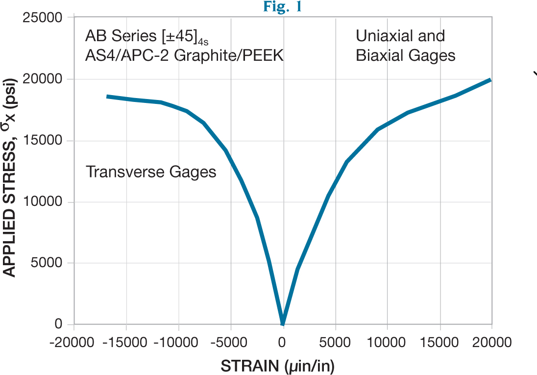
Fig. 1
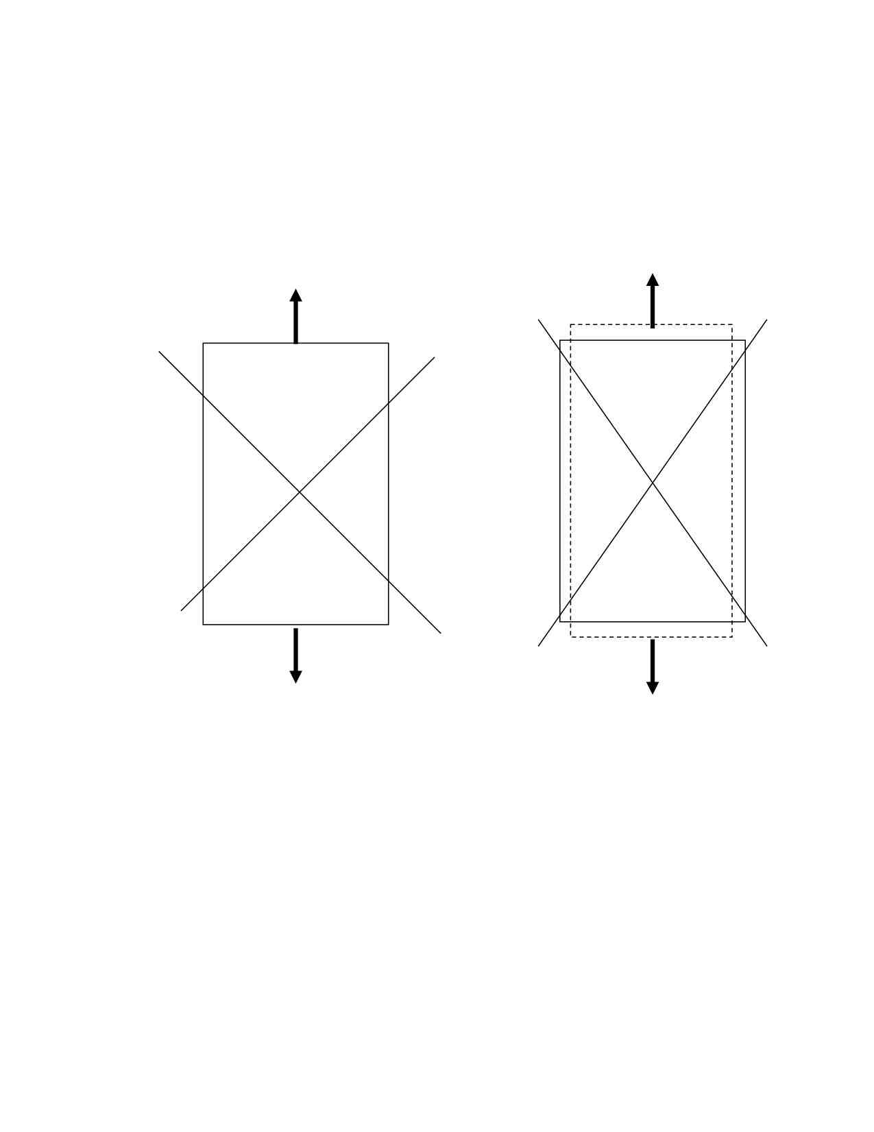
Fig 2
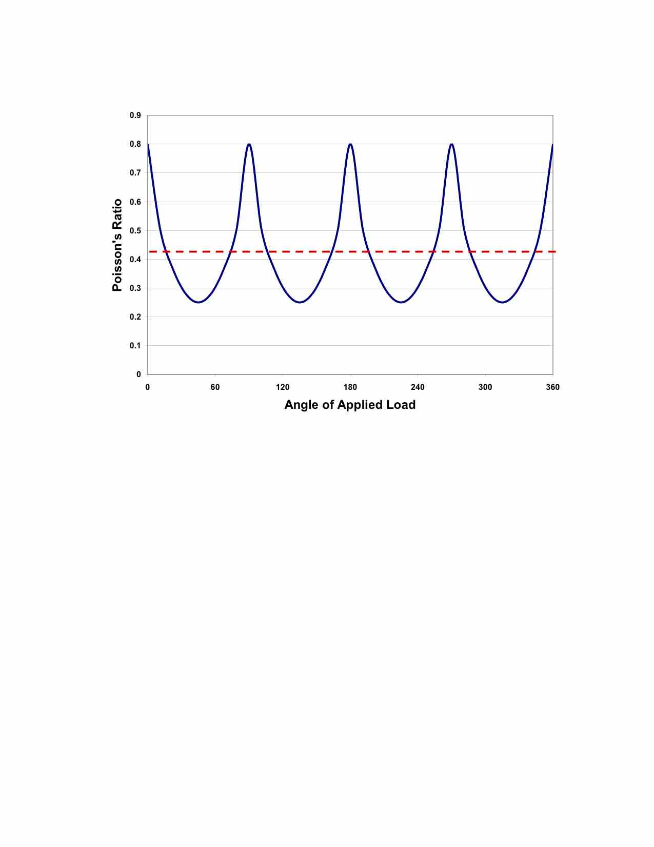
Fig. 3


The year is 1981. The scene, the R&D department of a major aircraft company.
“Uh, sir?” the young engineer stammers. “Sir? I am concerned about these stiffeners you want to bond onto the skins.”
“What’s the problem?” the elder engineer asks, kindly, but with a bit of condescension.
“Well, the skins are all ±45, which means they have a Poisson’s ratio of about 0.8, and when they load up, the shear between them and the stiffeners will be very high, and I am afraid the adhesive will fail.”
“Excuse me, what did you say about the Poisson’s ratio?” asks the older man.
“Well, for a ±45 laminate, the Poisson’s ratio is about 0.8 ….”
“Stop! Whatever gave you that idea?” he exclaims. “Everyone knows that Poisson’s ratios cannot go any higher than 0.5. What nonsense!”
“But sir, I have this little book on composites by Ashton, Halpin and Petit,” the younger engineer points out. (That might have been a tactical error. His favorite text — what he called his engineering “bible” — is a handbook published in 1898.) “And I programmed the equations into the Tectronix 4014, and the analysis says that the Poisson’s ratio of the skin laminate is 0.8, but in the stiffeners, only 0.25, and that will generate tremendous shears in the adhesive and ....”
“I don’t care what your computer says,” he interrupts. Reclassified from draftsman to engineer in the aftermath of World War II, the older man has learned engineering by the seat of his pants. Without formal training, he has nonetheless proved both intelligent and creative, and he has accrued many valuable years of experience — but all of it with metals. In 1981, all experienced engineers are “metals guys.” “Obviously you have done something wrong,” he declares. “Now don’t bother me about this anymore.”
A few months later, the two engineers witness the structural test of a wingbox with ±45 skins, unidirectional plies in the spar caps and quasi-isotropic hat stiffeners bonded to the underside of the skins.
“Sir,” says the younger. “I suggest that you not stand quite so close to the wingbox while it is being loaded.”
“Don’t worry, I’ll move away as we approach limit load,” replies the older man. “We are at less than a quarter of that right now.”
“But, sir, the bondline between the skin and the stiffeners, with that high Poisson’s ratio ....”
“What did I tell you about that?” he fires back. “Forget that nonsense!”
Each listens quietly as the load slowly increases. Crackling sounds come from the box, increasing in volume and frequency.
“Listen to that!” the elder man exclaims. “Composites are kind of like wood,” he guesses. “And just like the wooden dock on my lake-front property, they creak and moan under load. And just like my wooden dock, this baby is going to take a lot of load before it breaks!”
The young engineer inches farther back along the laboratory wall as the crackling and popping reach alarming levels. But the old man stands placidly next to the wingbox.
BANG!!!!! The old man jumps, his eyes huge. BANG!!!!! BANG!!!!!! “STOP LOADING!” he shouts as he backs rapidly away from the test fixture. The young engineer’s face is a kaleidoscope of concern for the elder engineer (will he have a heart attack?), worry (is it more than just the stiffeners popping off?) and relief (wow, I might be right!).
As the box is unloaded, they approach. Inside, the stiffeners lie loose in the bottom of the box. The rest of the box, after examination, looks fine.
The young engineer can no longer contain it. Vindication! Laughter bubbles up, is briefly choked back, then boils over. It’s catching. Waves of hilarity shake the room. Even the old man finally grins. The wingbox goes on to exceed ultimate load before any more failures occur. And the elder engineer? He retires a few months later.
Fast forward to 1997. At a respected engineering college that caters to the aerospace community, the now not-quite-so-young engineer encounters another metals guy during the oral defense of the engineer’s Ph.D. research. But this time she’s ready. She’s showing stress/strain graphs of specimens of various layups, loaded in tension, with biaxial gages. When she gets to the ±45 graph (see Fig. 1), one of the professors on her committee stops her.
“There must have been something wrong with those gages,” he observes. “That looks like the transverse strains were nearly as high as the axial strains.”
“Yes,” she replies. “The Poisson’s ratio of that laminate is just shy of 0.8.”
He literally jumps to his feet. “Impossible! The hydrostatic model requiring conservation of volume proves that cannot happen!” Obviously, he has been teaching undergraduate mechanics. She calmly turns off the projector light, walks to a blackboard and draws a rectangle, crossed with two diagonal lines (Fig. 2, left side).
“If I load the ±45 laminate in this direction,” she draws vertical arrows pointing up and down from the rectangle, “then the resin easily stretches and shifts, such that the fibers rotate and the transverse strain is also very high and, in fact, is about 80 percent of the axial strain.”
Then she erases the arrows and draws two more arrows parallel to one of the diagonal lines (Fig. 2, right side). “When we load it along the fiber direction,” she continues, “it is now, effectively, a 0/90 laminate, with a Poisson’s ratio in the range of 0.25 to 0.30.
“Now if we use the hydrostatic model in the planar direction only and load it equally around the edges,” she points out, “we find that the average Poisson’s ratio is less than 0.5, and the conservation of volume argument is still valid.” She draws a graph (Fig. 3) to illustrate her point.
She passes her orals and earns her Ph.D.


.jpg;maxWidth=300;quality=90;format=webp)


Related Content

IPSA acquires bonding adhesives based on MMA technology
IPS Adhesives (IPSA) introduces a line of adhesives using acrylate and MMA technology from L&L Products for the bonding of dissimilar materials such as metals and composites.
Read More
XlynX’s PlastiLynx PXN crosslinking primer enhances polymer adhesion
PFAS-free diazirine primer makes surfaces receptive to all manner of adhesives, including epoxies and polyurethanes, outperforming alternative options by 150-350%.
Read More
Film adhesive enables high-temperature bonding
CAMX 2024: Aeroadhere FAE-350-1, Park Aerospace’s curing modified epoxy, offers high toughness with elevated temperature performance when used in primary and secondary aerospace structures.
Read More
Pittsburgh engineers receive $259K DARPA award for mussel-inspired underwater adhesion
The proposed META GLUE takes inspiration from hydrogels, liquid crystal elastomers and mussels’ natural bioadhesives to develop highly architected synthetic systems.
Read MoreRead Next

“Structured air” TPS safeguards composite structures
Powered by an 85% air/15% pure polyimide aerogel, Blueshift’s novel material system protects structures during transient thermal events from -200°C to beyond 2400°C for rockets, battery boxes and more.
Read More
Developing bonded composite repair for ships, offshore units
Bureau Veritas and industry partners issue guidelines and pave the way for certification via StrengthBond Offshore project.
Read More
All-recycled, needle-punched nonwoven CFRP slashes carbon footprint of Formula 2 seat
Dallara and Tenowo collaborate to produce a race-ready Formula 2 seat using recycled carbon fiber, reducing CO2 emissions by 97.5% compared to virgin materials.
Read More