A400M wing assembly: Challenge of integrating composites
The Atlas military transport’s decade of development has lighted the path for Airbus wing development on the A350 and future programs.
Many of the articles published in HPC focus on the manufacture of a single composite component or structure. Often, these components become part of a larger product — an aircraft, spacecraft, racecar or some other complex structure in a high-performance application. But it’s rare that HPC is offered more than a glimpse of the machinery, processes and techniques used to assemble and integrate those components and many others into those larger structures.
And so it was that in October 2012, HPC editors were extended that rare invitation and paid a visit to the Airbus Military A400M Atlas military airlifter wing assembly facility in Filton, just north of Bristol in South Gloucestershire, U.K.
It’s at this facility that Airbus completes the complex task of integrating wing spars, wingskins and an assortment of other large carbon fiber composite structures into the A400M’s massive wing before equipping the structure with an array of complex systems, covering “fuel, electrics, pneumatics and hydraulics.” In addition, the plant installs all fixed and moveable structures, including trailing-edge devices (e.g., ailerons and flaps), leading edges and wingtips. This assembly effort represents one of the largest such operations in the world, producing a wing that weighs only 6500 kg/14,330 lb, but can contain and carry aloft as much as 25,000 kg/55,116 lb of fuel.
Among the assembly puzzles Filton engineers had to solve was how to manage the carbon fiber composites that are so critical to the wings’ structural and weight-saving success. “For us,” says Paul Evans, A400M lean consultant and HPC’s tour guide, “getting to grips with the carbon fiber was our biggest challenge. We’ve used carbon fiber in aircraft structures for many years, but this is the first time we’ve used it so extensively in such a large structure.”
A400M background
The A400M Atlas is the world’s newest and most advanced military airlifter, designed to ferry troops, equipment, vehicles, supplies, fuel and other materials in support of military operations. Scheduled for delivery in second quarter 2013, the Atlas is 45.1m/148 ft long, has a 42.4m/139-ft wingspan, measures 14.7m/48.25 ft tall and is powered by four Europrop TP400-D6 turboprop engines, each fitted with eight composite propeller blades. It has a maximum payload of 37,000 kg/81,600 lb, a range of 3,298 km/2,049 miles at maximum payload, a cruising speed of 780 kph/485 mph and a service ceiling of 11,300m/37,073 ft. As of October 2012, Airbus Military (Madrid, Spain) had fielded 174 orders for this new heavylifter.
More than 30 percent of the A400M’s aerostructure comprises composites, and the material is a vital part of Airbus’ efforts to reduce aircraft weight, increase fuel efficiency and extend service range. The largest single composite parts on the plane are the one-piece wingskins, each of which is 19m/62 ft long and 12 to 14 mm (0.47 to 0.55 inch) thick. When conceived and implemented, it represented one of the composites industry’s largest design, engineering and assembly challenges. Evans notes, in fact, that Airbus’ experience with carbon fiber composites on the A400M laid the groundwork for the company to do the same — more easily — on its A350 XWB. “It set up Airbus well to design and manufacture the more advanced A350,” says Evans.
The fact is that almost every assembly process Airbus has developed relative to composites on the A400M is a first for the company and, in some cases, a first in composites. The Filton team relied on lessons learned from Airbus composite experience at plants in Germany, Spain and France to develop innovative and efficient technical solutions. The spars and wingskins, says Evans, represented for Airbus the first use of carbon fiber composites in a wingbox application.
Stage 1
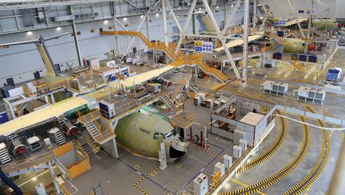
The A400M assembly facility is organized in three stages and in the shape of an inverted “U,” with Stage 1 at the left hand leg, Stage 2 along the arch and Stage 3 at the right hand leg. Stage 1 involves primary wing box structural assembly. Stage 2, comprising Pre-Equipping 1 and 2, includes addition of fasteners and minor structural work, wiring and other components in systems preparation, as well as testing. Stage 3 involves the addition of electrical harnesses, more wiring and piping, and full functional testing before shipment to Airbus’ A400M Final Assembly Line (FAL) in Seville, Spain.
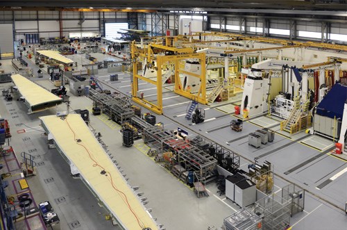
The most intensive composites work occurs at Stage 1. It’s here that Airbus receives the composite front and rear spars, manufactured by GKN Aerospace at its nearby Bristol, U.K. facility. Also integrated at Stage 1 are the composite upper and lower wingskins. These are manufactured via automated fiber and tape placement by Airbus at its plant in Stade, Germany. The wing in Stage 1 assembly the day of the HPC visit was for A400M aircraft number 13.
The first step at Stage 1 is spar assembly. Spars are delivered in two sections and joined with customized carbon fiber joint plates made by GKN Aerospace (Bristol, U.K.). The front spar is oriented flat in one of six holding fixtures, with the wing ribs and skins attached and assembled in a vertical orientation, with the spar serving as the base.
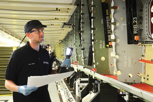
After the spar is joined, 24 aluminum ribs are attached at molded-in attachment points along the spar. (Evans says Airbus assessed use of carbon fiber composites in rib manufacture, but given the roughly 600 orders expected for the plane, the tooling for composites was deemed too expensive.)
After all of the ribs are attached, the wingskins are moved into place over the ribs and Airbus begins the most demanding work involved in the wing’s assembly: the drilling of 12,000 holes in a wing set. This is accomplished with what Airbus calls CAWDE (composites automated wing-drilling equipment) of which the company uses two in the Stage 1 assembly process. Years in development, each CAWDE unit comprises a set of tools designed and engineered specifically for this application. On the machinery side is a massive, 20-ft/6m tall by 10-ft/3m wide by 10-ft/3m deep, rail-mounted, 6-axis drilling system, designed and manufactured by Electroimpact Inc. (Mukilteo, Wash.). It’s made to move around each fixture in which a wing is held, drilling 90 to 95 percent of the 6,000 holes required for each wing. It uses a diamond-tipped cutting tool provided by Precorp (Spanish Fork, Utah), partially owned by Sandviken, Sweden-based machine tool supplier Sandvik Coromant. The tool is custom-designed to drill through a stack of carbon fiber and aluminum, providing pilot, drill, ream and countersink operations in one unit, says Evans. After all holes are drilled, the wingskin is removed, inspected and deburred if necessary. “We have eight days to drill 12,000 holes,” reports Evans.
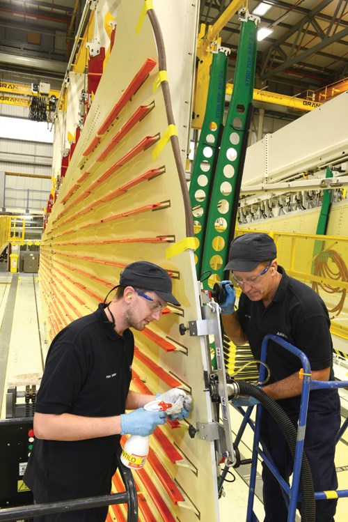
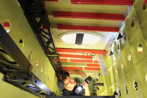
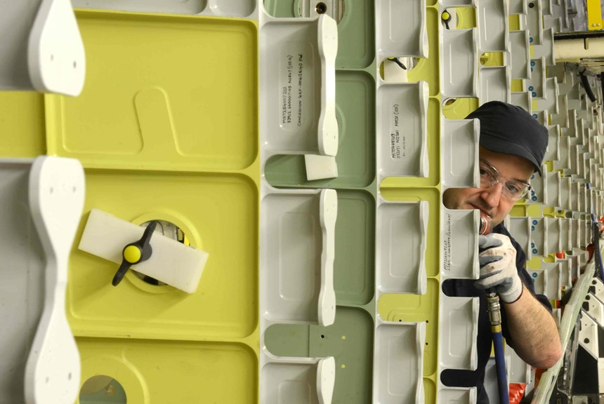
After deburring, the wingskin is repositioned over the ribs and spars and the process of actually fastening the skins begins. Bolts used to attach the wingskins must be accessed from outside and inside the wing. To do this, technicians crawl into the wings via pre-cut fuel tank access holes in the skins. From the inside, they provide the guidance and torque required, respectively, to position and tighten the bolt as technicians insert them from the outside.
Because the wings must contain fuel, each bolt is coated with a sealant to prevent leakage, “We just can’t have any fuel leaks,” says Evans. “For that reason we have very tight tolerances.”
Stage 2
After drilling, bolting and sealing are complete, the wing weighs about 3,500 kg/ 7,716 lb. At this point, the wing is removed from its fixture via vacuum lifting equipment, transported via crane to the first of two Stage 2 workstations, called Pre-Equip 1, and oriented flat on a new work fixture that gives operators and installers easy access to the wing’s leading and trailing edges.
At this stage, Airbus conducts a series of metrology checks with laser trackers and photo-imagery to verify that the wing meets a variety of critical dimensional specifications. Workers also do some drilling of the leading edge before sending the entire structure on to the second Stage 2 workstation, Pre-Equip 2.
Pre-Equip 2 sees the installation of the initial equipment needed to complete assembly of the wing. This includes harness brackets (which are positioned with the aid of laser-projection equipment and adhesively applied) and weight-supporting brackets for the leading and trailing edges. Once they are installed, Airbus conducts a tank pressure test, first with air, then with hydrogen/nitrogen, to verify the integrity of the fuel-storage capability of the wing.
Stage 3
After the wing passes the pressure test, it’s on to Stage 3, the Final Equip line, which handles the final stage of wing assembly before it’s sent on to the A400M FAL. Most of the heavy-duty hardware is installed on this line, followed by wing actuation and testing.
Included here is installation of electrical wiring, air bleeds, fire protection equipment, fixed leading edges, ailerons, spoilers and flaps. Notable here is the installation of carbon fiber composite fuel pipes throughout the wing. The pipes are fabricated and supplied by Adel Wiggins Inc. (Los Angeles, Calif). It’s at this stage that Airbus also installs one more carbon fiber component of note: A driveshaft for flap actuation, provided by Goodrich Corp.’s Crompton Technology Group (CTG, Banbury, Oxfordshire, U.K.). The shafts, about 1m/3.3 ft long and 40 mm/1.57-inches in diameter, are filament wound carbon fiber and feature stainless steel end fittings. CTG reports that its shafts go through a minimum four- to six-lifecycle qualification process and are designed for a minimum operating life of 20 years.
After all components are installed and attached, the wing attains its full weight of ~6,500 kg/~14,330 lb and goes through a full function test of all components to verity that the wing is operating as it should. It’s then ready to be sent to the FAL in Spain.
Since the A400M was first conceived 10 years ago, and the decision was taken to use carbon fiber composites as extensively as Airbus did in the wings, other aircraft have come to market that use composites in similar ways — Boeing’s 787, the Airbus A350, the Bombardier CSeries, and more. In many ways, however, the A400M Atlas started the trend, set the standard and, in the military market, remains the largest aircraft to use composites so aggressively. Evans stressed repeatedly to HPC that composites lessons learned on the A400M Atlas wing assembly line have been applied throughout the Airbus organization, and these lessons will benefit Airbus design and manufacturing practice for years to come.“This was a scale of composites use in a structure Airbus had not tried before,” says Evans. “It took a lot of effort and learning to get this far, but it certainly has been worth it.”
Related Content
TU Munich develops cuboidal conformable tanks using carbon fiber composites for increased hydrogen storage
Flat tank enabling standard platform for BEV and FCEV uses thermoplastic and thermoset composites, overwrapped skeleton design in pursuit of 25% more H2 storage.
Read MorePlant tour: Albany Engineered Composites, Rochester, N.H., U.S.
Efficient, high-quality, well-controlled composites manufacturing at volume is the mantra for this 3D weaving specialist.
Read MoreInfinite Composites: Type V tanks for space, hydrogen, automotive and more
After a decade of proving its linerless, weight-saving composite tanks with NASA and more than 30 aerospace companies, this CryoSphere pioneer is scaling for growth in commercial space and sustainable transportation on Earth.
Read MoreCryo-compressed hydrogen, the best solution for storage and refueling stations?
Cryomotive’s CRYOGAS solution claims the highest storage density, lowest refueling cost and widest operating range without H2 losses while using one-fifth the carbon fiber required in compressed gas tanks.
Read MoreRead Next
Plant tour: Daher Shap’in TechCenter and composites production plant, Saint-Aignan-de-Grandlieu, France
Co-located R&D and production advance OOA thermosets, thermoplastics, welding, recycling and digital technologies for faster processing and certification of lighter, more sustainable composites.
Read More“Structured air” TPS safeguards composite structures
Powered by an 85% air/15% pure polyimide aerogel, Blueshift’s novel material system protects structures during transient thermal events from -200°C to beyond 2400°C for rockets, battery boxes and more.
Read MoreVIDEO: High-volume processing for fiberglass components
Cannon Ergos, a company specializing in high-ton presses and equipment for composites fabrication and plastics processing, displayed automotive and industrial components at CAMX 2024.
Read More



.jpg;maxWidth=300;quality=90)

