
Equibiaxial flexural strength testing of fiber-reinforced ceramics
In my last column, I discussed uniaxial flexural strength testing of fiber-reinforced ceramics, that is, simple three- or four-point bending of a strip of material of rectangular cross section (see "Learn More," at left). As was noted, the strength of this test specimen is sensitive to machining defects at its edges. Also, in many applications of fiber-reinforced ceramics (and unreinforced ceramics), the stress state is not uniaxial, but rather biaxial.


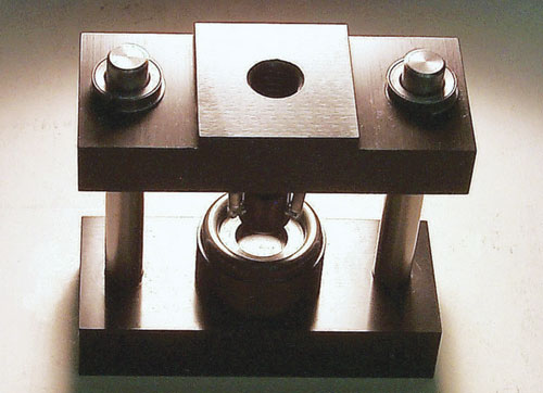
Fig. 1: ASTM C 1499 test fixture (ring-on-ring, assembled). Source Don Adams Source Don Adams
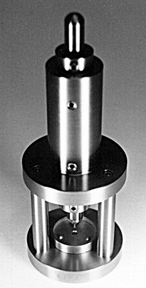
Fig. 2: ASTM F 394, test fixture (three-ball specimen support, center loading). Source Don Adams
In my last column, I discussed uniaxial flexural strength testing of fiber-reinforced ceramics, that is, simple three- or four-point bending of a strip of material of rectangular cross section (see "Learn More," at left). As was noted, the strength of this test specimen is sensitive to machining defects at its edges. Also, in many applications of fiber-reinforced ceramics (and unreinforced ceramics), the stress state is not uniaxial, but rather biaxial. Based on these considerations, biaxial flexural tests have been developed, at least two of which have become commonly used ASTM and ISO standards.
One of the two is ASTM C 1499,1 introduced in 2001 and currently the primary ASTM standard for biaxial testing. In the ASTM C 1499 test method, a thin circular disk (the standard also permits the use of a thin square plate) is supported on a ring and loaded by a ring of smaller diameter. For that reason, it is commonly referred to as a ring-on-ring test. The goal is to induce a biaxial failure stress away from the edges of the specimen that can be calculated using simple, small-deflection plate theory.
ASTM C 1499 is a broader version of ISO 13356,2 published in 1997 and entitled, "Implants for Surgery — Ceramic Materials Based on Yttria-Stabilized Tetragonal Zirconia (Y-TZP)." As indicated in its title, ISO 13356 was originally directed toward a specific class of ceramics. Although its current applications are no longer so limited, the ISO 13356 standard defines all of the specimen and fixture parameters — specifically, specimen diameter (36 mm/1.42 inches), specimen thickness (2 mm/0.08 inch), support ring diameter (30 mm/1.18 inch), loading ring diameter (12 mm/0.47 inch) and ring cross-sectional radii (2 mm/0.08 inch). By contrast, ASTM C 1499 was conceived and written as a generic standard, intended for use with a range of monolithic, whisker- or particle-reinforced, and discontinuous-fiber-reinforced ceramic composites. The standard, therefore, defines acceptable ranges for these dimensions. Usually, a material of given thickness, h, is to be tested. The other specimen and test fixture dimensions must be related to this thickness and to the strength and stiffness of the test material.
Unfortunately, the required relationships are scattered throughout the text of the ASTM C 1499 standard in equation forms that tend to confuse and intimidate the prospective user. They are collected here and presented in more logical formats, as follows:
(E/xƒ)1/2h ≤ Ds ≤ 10h
This expression relates the required support ring diameter, Ds, to the specimen thickness, h, in terms of the expected equibiaxial fracture strength, xƒ, and modulus of elasticity, E, of the material being tested, assuring that small-deflection plate theory is applicable. Note that, if the ratio E/xƒ is greater than 100, a value of Ds = 10h is to be used.
2 ≤ (D- Ds)/h ≤ 12
This relates specimen diameter, D, to support ring diameter, Ds, for a given specimen thickness, h. That is, it defines the amount of specimen overhang. The standard suggests that the lower limit is generally sufficient, except in those cases where the edge finish of the specimen is poor. In such cases, a greater overhang may be required to prevent edge failures.
0.2 ≤ DL/Ds ≤ 0.5
This defines the loading ring diameter, DL.
0.5h ≤ r ≤ 1.5h
This relates the cross-sectional radius, r, of the loading and support rings to the specimen thickness.
The downside of designing the specimen and fixture to the material thickness to be tested, as specified in ASTM C 1499, is that there is no standardized fixture size. Each fixture must be custom made. A photograph of one such fixture is shown in Fig. 1.
The other commonly used biaxial test method consists of a circular disk specimen resting on three balls and loaded at its center by a small-diameter, flat-ended probe. The original standard was ASTM F 394,3 first issued in 1974. This standard was discontinued in 2001, presumably because of the introduction of the ring-on-ring test method (ASTM C 1499) that same year. However, ISO Standard 6872,4 first issued in 1984, is still active, using the same fixture design, although not the same dimensions.
ASTM F 394 specified the diameter of the test specimen (1.25 inch/31.75 mm) and the configuration of the test fixture. The latter consisted of three balls, each 0.125 inch/3.18 mm in diameter, spaced equally around a 1-inch/25.7-mm diameter circle to support the specimen, which was center-loaded by a 0.063-inch/1.6-mm diameter flat-ended probe. Specimen thickness was not specified other than that it had to be sufficient to limit the maximum specimen deflection to one-half the specimen thickness (again, to permit the use of small-deflection plate theory when calculating the biaxial stress). These specifications permitted a standardized test fixture, such as the one shown in Fig. 2.
There is no particular reason why the overall configuration of the fixture depicted in Fig. 1 (a top plate moving along two alignment rods) should differ so significantly from that of Fig. 2 (a central probe moving in a fixed housing). Both accomplish the same end. The difference is primarily attributable to the fact that ASTM F 394 suggested a specific overall geometry (also adopted by ISO 6872), while ASTM C 1499 and ISO 13356 did not, permitting test fixture manufacturers the freedom to construct fixtures of their own design as long as they meet the functional criteria.
ASTM C 1499 in particular, a relatively new standard, is becoming increasingly popular as it becomes better known. But no matter which method and fixture are used, the test results are reliable only if the maximum biaxial stress occurs in the central region of the specimen, away from the specimen edges, on the tensile surface (the surface opposite to that being loaded). Postfailure examination of the failed specimen will usually determine if a valid failure has occurred. Adhesive tape applied to the compressive (upper) surface of the specimen will help contain the fragments for postfailure analysis.
References
2ISO Standard 13356 (First Edition, 1997), "Implants for Surgery — Ceramic Materials Based on Yttria-Stabilized Tetragonal Zirconia (Y-TZP)," International Organization for Standardization (Zurich, Switzerland), first issued in 1997.
3ASTM Standard F 394-76 (Reapproved 1991, Discontinued 2001), "Biaxial Flexure Strength (Modulus of Rupture) of Ceramic Substrates," American Society for Testing and Materials, (W. Conshohocken, Pa.), first issued in 1974.
4ISO Standard 6872 (Second Edition, 1995), "Dental Ceramic," International Organization for Standardization (Zurich, Switzerland), first issued in 1984.


Related Content

Notched testing of sandwich composites: The sandwich open-hole flexure test
A second new test method has been standardized by ASTM for determining notch sensitivity of sandwich composites.
Read More
Measuring ply-wise deformation during consolidation using embedded sensors
Strip-type shape sensor method claims real-time measurement of ply-wise deformation.
Read More
Numerical tool with mean stress correction demonstrated for fatigue life estimation of thermoplastic composites
To aid design of fatigue-resistant structures, Econ Engineering has developed an algorithm to evaluate ply-based cyclic stiffness degradation combined with an FE failure check, validated for a CF/PAEK pressure vessel.
Read More
Testing to support composite bolted joint analysis
An overview of ASTM Standard Guide D8509, and its coupon-level mechanical testing of design properties for analyzing composite bolted joints.
Read MoreRead Next

Flexural testing of fiber-reinforced ceramics
Because of their brittle nature, ceramics, fiber-reinforced or unreinforced, are difficult to test in pure tension, compression and shear, primarily due to difficulties in gripping and uniformly loading the brittle specimen.
Read More
VIDEO: High-volume processing for fiberglass components
Cannon Ergos, a company specializing in high-ton presses and equipment for composites fabrication and plastics processing, displayed automotive and industrial components at CAMX 2024.
Read More
“Structured air” TPS safeguards composite structures
Powered by an 85% air/15% pure polyimide aerogel, Blueshift’s novel material system protects structures during transient thermal events from -200°C to beyond 2400°C for rockets, battery boxes and more.
Read More