
Hybrid analysis: Making the most of FEA by leveraging traditional analysis
CW guest columinst Collin Petersen (Janicki Industries, Sedro-Woolley, WA, US) suggests the use of more traditional analysis methods, where it is sensible to do so, making your finite element analysis (FEA) significantly simpler in the process.

Collin Petersen, P.E., has worked with Janicki Industries (Sedro-Woolley, WA, US) since 2008. As lead design engineer, he heads a team that completes composite layup design, stress analysis and a wide variety of tooling designs, including large fiber placement mandrels, overhead handling equipment and complex assembly and transportation fixtures.
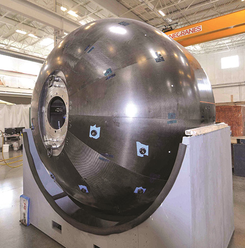
Fig. 1: Completed carbon fiber/epoxy composite shell tool with metallic spindle and support structure. Source: Janicki Industries
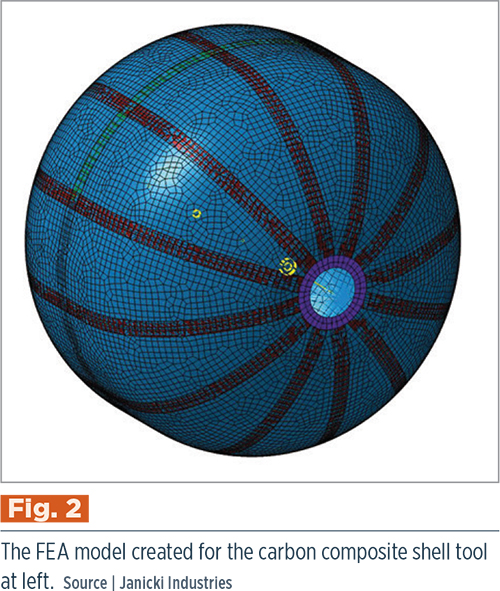
Fig. 2: The FEA model created for the carbon composite shell tool at left. Source: Janicki Industries


Finite element analysis (FEA) is an invaluable tool for design engineers, but in many industries, “factors of safety” requirements have not caught up with the fidelity of these modern techniques. By using more traditional methods where it is sensible to do so, you can align your analysis technique with the expectation of these established safety factors and make your FEA significantly simpler in the process.
At Janicki Industries, we specialize in large-scale composite structures and tools for a variety of markets. Our customers face a common challenge: Gaining confidence in the structural elements of the tooling and/or completed parts. Many of our projects are prototypes or “one-off” tools with tight cost and schedule constraints; for example, a single-use tool that weighs thousands of pounds, with pick points for lifting, or a custom fiberglass-cored residential roof, with snow and wind load requirements. Unique projects like these require flexibility and creativity from engineers tasked with design and analysis. We have developed a toolbox of industry-accepted techniques that merge familiar traditional methods with modern FEA, enabling us to very quickly analyze and optimize designs.


These methods also can provide a valuable sanity check against the results of a more in-depth FEA analysis. My high school calculus teacher, Mr. Wright (no joke), impressed upon all of his students, “you have to be smarter than your calculator.” Implementing techniques like the following can give valuable context and verification to go along with all of those colorful FEA stress plots.
Simplifying a composite shell analysis
One example is a large (≈2.5m diameter) layup mandrel fabricated from several carbon fiber/epoxy facesheet segments tied together with Invar rings and supported on a steel spindle (see Fig. 1). To analyze this tool under automated fiber placement (AFP) machine load conditions in an efficient manner, we combined a simplified FEA model with some more traditional analysis techniques.
Using laboratory test data and closed form techniques to calculate laminate properties, we were able to greatly simplify the effort needed to model the composite shell. In this case, our laminate was quasi-isotropic and used a material we have comprehensive laboratory test results for at the laminate level, so this shell was a good candidate for what is often called a “black aluminum” or “smeared composite property” technique. By inputting the laminate stiffness as an isotropic property, and then comparing the resulting stresses against allowables based on test data, we were able to verify the strength and stiffness of the facesheet of this layup mandrel without having to generate a ply-by-ply composite property card in our FEA pre-processor.
This was a relatively simple task for a quasi-isotropic laminate, but there are ways to simplify the analysis of even much more complex laminates. Janicki Industries uses HyperSizer - Collier Research Corporation (Collier Research Corp., Newport News, VA, US) to automate the generation of laminate level properties and enter them into our pre-processor. Because it leverages the speed of closed-form techniques for analyzing the local laminate in combination with the versatility of an FEA model, it enables very fast iteration and optimization of laminate schedules that would not be possible by entering the lamina or ply-level properties directly into the pre-processor.
We also were able to simplify other aspects of the FEA model. For instance, we modeled the steel spindle that runs the length of the tool using simple beam elements. Although this technique does not allow for plotting the spindle’s detailed stress profile in the post-processer, it does accurately capture the steel pipe’s stiffness and the AFP machine’s boundary conditions. The spindle was connected to the composite shell’s ends using a fastened analysis connection in CATIA V5’s Elfini Structural Analysis product (Dassault Systèmes, Velizy-Villacoublay, France). The loads were extracted from the critical locations along the spindle and the pipe was analyzed using simple hand calculations.
Welds were handled similarly. Rather than carefully modeling the weld’s shape, the loads at the weld locations were extracted from the FEA results and input into simple weld-strength hand calculations as laid out by Shigley and Mischke in their classic text, Mechanical Engineering Design1. This allows for very quick iteration of the weld size needed for the desired factor of safety.
The fastener patterns connecting the spindle to the composite shell were similarly analyzed. The loads at that connection were extracted from the FEA results in the post-processer and fed into a Mathcad (PTC, Needham, MA, US) template that uses hand calculation methods described in the AISC’s Steel Construction Manual2 for eccentrically loaded bolt groups with eccentricity normal to the plane of the faying surfaces. Other hand calculations can be found in Shigley and Mishcke1 and other references. This allows the engineer to create a simple FE model that does not include fastener details. The size and number of fasteners then can be quickly iterated to optimize the fastener pattern to the factor of safety without revising/re-solving the FEA.
Another method for modeling fastened connections, when greater fidelity is required, is to model each fastener with a simple node-to-node connector element. To accurately represent the connection’s stiffness, the Huth method3 can be used to calculate each fastener’s equivalent stiffness. This method, created by fitting a curve to a large set of experimental data, more accurately distributes the load among fasteners and is valid for both riveted and bolted joints in metallic and carbon/epoxy composite structures.
Analyzing complex assemblies, especially when they include composite components, can be intimidating. Building a ply-level FE model of the composite elements and then modeling all of the fastened connections to other components is very time-consuming. But analyzing such assemblies doesn’t have to be that difficult. A combination of tried-and-true closed-form analysis techniques with FEA tools can produce a verifiable analysis with a lot less effort and a lot more confidence.
References
1Shigley, et. al., Mechanical Engineering Design, 10th Edition, McGraw-Hill, 2014.
2Steel Construction Manual, American Institute of Steel Construction (AISC, Chicago, IL, US), 14th Ed., 2011.
3Huth, H., “Influence of Fastener Flexibility on the Prediction of Load Transfer and Fatigue Life for Multiple-Row Joints,” Fatigue in Mechanically Fastened Composite and Metallic Joints, ASTM STP 927, John M. Potter, Ed., ASTM International (W. Conshohocken, PA, US), 1986, pp. 221-250.


.jpg;maxWidth=300;quality=90;format=webp)


Related Content

Proper application of semi-permanent mold release systems
Performing regular maintenance of the layup tool for successful sealing and release is required to reduce the risk of part adherence.
Read More
3D-printed CFRP tools for serial production of composite landing flaps
GKN Aerospace Munich and CEAD develop printed tooling with short and continuous fiber that reduces cost and increases sustainability for composites production.
Read More
Mold 3D printing helps automate composite bathtub, shower production
As part of its efforts to automate as much of its production process as it can, Lyons Industries acquired a Massivit 10000 additive manufacturing system to quickly produce high-performance molds and support fixtures.
Read More
ATLAM combines composite tape laying, large-scale thermoplastic 3D printing in one printhead
CEAD, GKN Aerospace Deutschland and TU Munich enable additive manufacturing of large composite tools and parts with low CTE and high mechanical properties.
Read MoreRead Next

Plant tour: Daher Shap’in TechCenter and composites production plant, Saint-Aignan-de-Grandlieu, France
Co-located R&D and production advance OOA thermosets, thermoplastics, welding, recycling and digital technologies for faster processing and certification of lighter, more sustainable composites.
Read More
“Structured air” TPS safeguards composite structures
Powered by an 85% air/15% pure polyimide aerogel, Blueshift’s novel material system protects structures during transient thermal events from -200°C to beyond 2400°C for rockets, battery boxes and more.
Read More
VIDEO: High-volume processing for fiberglass components
Cannon Ergos, a company specializing in high-ton presses and equipment for composites fabrication and plastics processing, displayed automotive and industrial components at CAMX 2024.
Read More