The challenge of identifying test procedures for recycled carbon fiber composites
With growing use of recycled carbon fiber composites, the identification of mechanical testing procedures for rCF becomes increasingly important … and challenging.

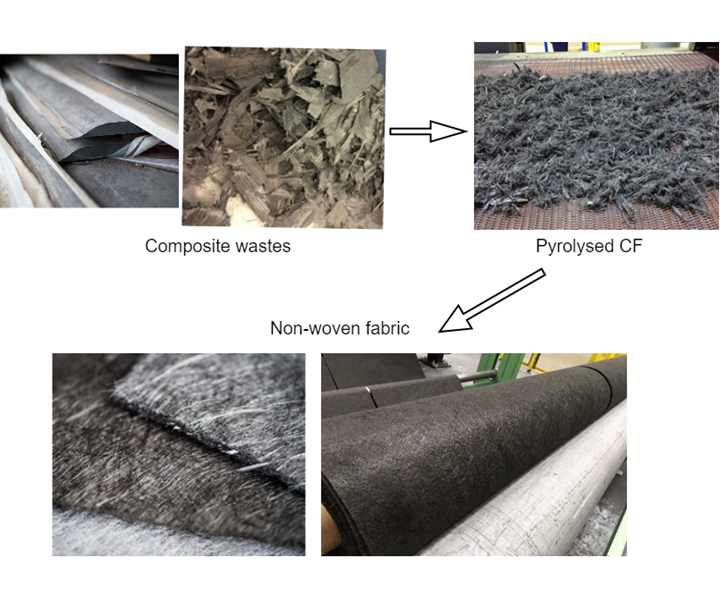
Fig. 1 Carbon fiber recycling process. Source | ELG Carbon Fibre
The exponential increase in the global demand for carbon fiber products — and the waste associated with their consumption — raises a lot of sustainability issues. Carbon fiber has an embodied energy as high as that of aluminum, that is widely recycled, and the disposal of carbon fiber waste has a serious impact on the circular economy. As a result, recycling techniques such as hydrolysis, solvolysis and pyrolysis have been gaining momentum over the last couple of decades1. For example, the chain bed pyrolysis technique, employed by ELG Carbon Fibre Ltd. (Coseley, U.K.), has been set up at an industrial scale and was reclaiming more than 1,300 metric tonnes of CF per year, as of 20172,3.
The major technological challenge with pyrolysis, however, is its inability to recover carbon fiber in the same form as its source. The end product of pyrolysis recycling is a fluffy, entangled mass of discontinuous fibers (see Fig. 1). An efficient, cost-effective method for handling recycled carbon fibers (rCF) is conversion of fibers into a textile fabric, much like converting wool fleece into fabrics. Using this method, ELG converts rCF into randomly distributed, dry laid, needle-punched, nonwoven fabrics that are compression molded in epoxy resin. Due to the porous nature of these fabrics, however, the resulting laminates typically achieve only around 30% fiber volume fraction.
Because of these material behavior properties, rCF composites are dissimilar to conventional, long and continuous fiber-reinforced virgin CF (vCF) composites, and likewise exhibit different properties. To understand the capabilities, mechanical behavior and design limits of rCF composites, it is essential to develop a reliable dataset and characterize them with suitable test methods. Unfortunately, the codes and standards for macro-scale testing were developed for continuous fiber-reinforced composites in mind. In addition, a number of discrepancies at coupon level testing exist in literature and industry even for conventional composites4. Adding further complications, some OEMs, such as Airbus, use their own in-house test practices to characterize vCF composites5. The introduction of rCF composites with their unique reinforcement architecture in discontinuous, nonwoven, composites further raises this ambiguity in composites testing protocols. Additionally, there is a wide choice of test methods for the measurement of a single property. Though identification of the most suitable test is time-consuming, it is fundamental for understanding the material’s mechanical behavior. The primary objective of the authors’ research was to determine if nonwoven rCF composites would require the development of a specific set of standard testing protocol, to evaluate and analyze its use in existing and potential new applications.
The guidance for a test method that is seemingly as straightforward as a static tensile test becomes unclear in the case of discontinuous, nonwoven rCF composites. The common practice is to use straight-sided rectangular coupons due to the simplicity of specimen preparation. For rCF composites, however, the use of rectangular coupons as described by ASTM D3039 or ISO 527-4 type 2 or 3, with or without end tabs, has resulted in failures at or near the tabs due to a poor stress transfer into the gauge length of the specimen. From a sample size of 150 rectangular specimens, fewer than 12.5% produced an acceptable gauge failure.
There are a number of possible causes for this, including poor specimen preparation, load introduction method, grips, test speed, specimen geometry, etc. A bow-tie specimen, as trialed by the U.S. Army Materials and Mechanics Research Centre for random glass fiber composites, did not yield improved results for rCF composites either6. In this trial, the use of dogbone geometry, as described by ASTM D638, resulted in much-improved performance with more than 80% of the specimens failing within the central gauge region, as depicted in Figure 2. This specimen design has a significant impact on tensile characteristics, as the rectangular geometry specimens tend to fail prematurely.
Our study, using identical rCF composite rectangular and dogbone samples, resulted in a 10% and 20% reduction in tensile strength and stiffness, respectively, for the rectangular samples as compared to the dogbone samples. Improved geometry design in tension load was also evident in cyclic fatigue. At a particular stress level in a tension-tension fatigue loading, a rectangular coupon could fail anywhere between a few hundred cycles to more than 3 million fatigue cycles, whereas the variability in cycles to failure for dogbone coupons was much lower.

Fig. 2. Improvement in stress transfer to sample gauge length in dogbone specimens. Source | Karthik Krishna Kumar
A similar pattern was observed when both out-of-plane and in-plane shear were evaluated. Although out-of-plane shear or interlaminar shear is only a quality control test, a number of test methods have been established for its assessment, such as short beam shear (SBS) test methods described by ASTM D2344 and ISO 14130, double notch shear (DNS) by ASTM D3846 and the very recently developed Double Beam Shear (DBS) by ISO 19927. Unfortunately, none of these tests presented the desired result of a pure interlaminar shear failure with rCF composites. The common tendency was to fail by undesirable modes such as tensile or crushing, rather than a shear-dominated failure in the specimen.
A method that is quite successful in subjecting a material, composite or metal, to a state of pure shear is the Iosipescu shear test, which uses a V notch geometry specimen. However, for the evaluation of interlaminar shear, ASTM D5379 recommends the use of a 76-millimeter-thick panel that is quite impossible to manufacture without the introduction of defects. The alternative was to bond panels together to 76 millimeters thick, which on successful specimen manufacturing could potentially result in a crushing failure at the grip section of the V notch specimen. A remodified standard specimen design reconstructing only the critical section of the V notch specimen avoided this problem and resulted in the generation of a pure interlaminar shear failure in rCF composites.
The Iosipescu shear test was, however, inapplicable for in-plane shear testing in rCF composites. The tendency was to fail by a tensile-dominant failure that is expected, given its fiber distribution in the XY plane of the laminate. A possible alternative could be the plate twist method as described by ISO 15310, generally used for wood composites. It is clear that the nature of the fiber reinforcement architecture has a significant effect on the mechanical behavior and material response for basic static macro-scale coupon level tests. Furthermore, the mechanical behavior of rCF composites in cyclic loading has been found to be quite unlike that in conventional vCF composites or short fiber reinforced composites.
Recycled carbon fiber composites have a number of material processing variables that influence mechanical characteristics, including molding process, fiber content, fiber modulus grade, resin grade of the source form of recyclates and fiber-matrix interaction. The analysis of these parameters is futile and cumbersome without the development of dedicated standard testing practices for a material that has freshly entered the market. The British Standards Institution (BSI) has addressed specifications for unconventional composite systems like textile glass-reinforced plastics, sheet molding compound (SMC) and bulk molding compound (BMC) thermoset composites, wood polymer/natural fiber composites, pultruded reinforced composites and more with dedicated standards that identify applicable test methods. Recycled carbon fiber composites now require the same approach to enable reliable characterization.
References:
1Job, S., Leeke, G., Mativenga, P.T., Oliveux, G., Pickering, S. and Shuaib, N.A., 2016. Composites recycling: Where are we now. Composites UK Ltd.: Berkhamsted, UK.
2Jacob, A. (2019). Building confidence in recycled carbon fiber. [online] Available at: https://www.compositesworld.com/blog/post/building-confidence-in-recycled-carbon-fiber [Accessed 29 Jul. 2019].
3Inston, D. (2019). ELG Carbon Fibre open house showcases recycling technology. [online] Available at: https://www.compositesworld.com/news/elg-carbon-fibre-open-house-showcases-recycling-technology [Accessed 29 Jul. 2019].
4Adams, D. (2019). Mechanical testing of textile composites. [online] Available at: https://www.compositesworld.com/blog/post/mechanical-testing-of-textile-composites [Accessed 29 Jul. 2019].
5Spendley, P.R., 2012. Design allowables for composite aerospace structures.
6Oplinger, D.W., Gandhi, K.R. and Parker, B.S., 1982. Studies of Tension Test Specimens for Composite Material Testing (No. AMMRC-TR-82-27). Army Materials and Mechanics Research Centre Watertown Ma.
Karthik Krishna Kumar is a Ph.D. student at Oxford Brookes University, U.K. His research entails the development of appropriate test practices for recycled, nonwoven carbon fiber composite systems, assessment of their fatigue behavior and environmental durability, for the safe and sustainable use of carbon fiber in practical applications.
Related Content
The potential for thermoplastic composite nacelles
Collins Aerospace draws on global team, decades of experience to demonstrate large, curved AFP and welded structures for the next generation of aircraft.
Read MoreNatural fiber composites: Growing to fit sustainability needs
Led by global and industry-wide sustainability goals, commercial interest in flax and hemp fiber-reinforced composites grows into higher-performance, higher-volume applications.
Read MoreWelding is not bonding
Discussion of the issues in our understanding of thermoplastic composite welded structures and certification of the latest materials and welding technologies for future airframes.
Read MorePEEK vs. PEKK vs. PAEK and continuous compression molding
Suppliers of thermoplastics and carbon fiber chime in regarding PEEK vs. PEKK, and now PAEK, as well as in-situ consolidation — the supply chain for thermoplastic tape composites continues to evolve.
Read MoreRead Next
The state of recycled carbon fiber
As the need for carbon fiber rises, can recycling fill the gap?
Read More“Structured air” TPS safeguards composite structures
Powered by an 85% air/15% pure polyimide aerogel, Blueshift’s novel material system protects structures during transient thermal events from -200°C to beyond 2400°C for rockets, battery boxes and more.
Read MoreDeveloping bonded composite repair for ships, offshore units
Bureau Veritas and industry partners issue guidelines and pave the way for certification via StrengthBond Offshore project.
Read More


.jpg;maxWidth=300;quality=90)


