Welding is not bonding
Discussion of the issues in our understanding of thermoplastic composite welded structures and certification of the latest materials and welding technologies for future airframes.
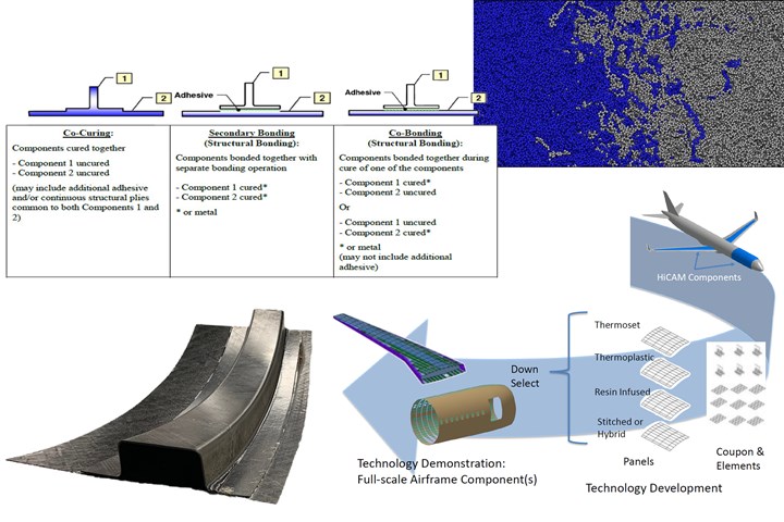
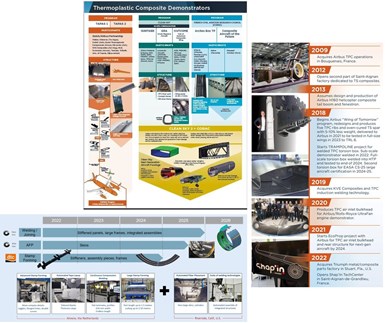
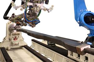
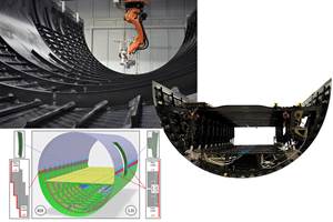
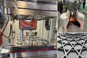
Photo Credit: (top left clockwise) Definition of a bonded joint by the Federal Aviation Administration; Simulation of polymer chain diffusion in a welded thermoplastic composite joint by Boise State University; Validation of manufacturing technology by NASA HiCAM program; Welded curved hat stiffener to skin section by Collins Aerospace.
Thermoplastic composite (TPC) welding has been a key topic for CW since the March 2006 feature, “Thermoplastic composites gain leading edge on the A380”. That article described GKN Fokker’s (Hoogeveen, Netherlands) development of resistance welding for the Airbus A380 J-nose (inboard fixed leading edge of the wing). More than 15 year later, a significant amount of progress has been achieved in welded TPC structures (see “Thermoplastic composites welding advances …”). And yet, some debate continues about how such structures should be certified. No one debates that welded TPC structures must show test results validating the joint design, materials and process used as well as their ability to remain flightworthy during their service life. However, a welded TPC structure is not bonded, and thus, should not be certified as a bonded joint.
This article discusses the definition of bonding versus welding, as well as efforts being made to advance certification of welded TPC structures, including the Hi-Rate Composite Aircraft Manufacturing (HiCAM) project, part of NASA’s Sustainable Flight National Partnership (SFNP) to enable 25-30% energy efficiency improvements in next-gen commercial transport aircraft.
What is bonding?
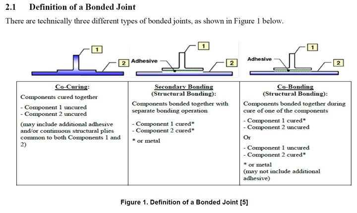
The definition of a bonded joint is put forward and discussed by Cynthia Ashforth and Larry Ilcewicz from the Federal Aviation Administration (FAA) in the 2018 report, “Certification of Bonded Aircraft Structure and Repairs”:
“FAA guidance only recognizes secondary bonding and co-bonding as bonding processes with multiple interfaces (i.e., composite-to-composite, composite-to-metal, or metal-to-metal), where at least one of the interfaces requires additional surface preparation prior to bonding. In the case of co-curing, while an adhesive may be used between two laminates, the laminates and any adhesive are uncured and therefore do not have any surface preparation prior to bonding and cure.”
Note that co-curing is not considered bonding. Co-cured composites have been certified for wings on the Boeing 777 and for the fuselage and wings on the Boeing 787 and Airbus A350. Notably, these were certified as co-cured, not bonded structures.
“In co-curing, the prepreg laminates in the mated parts are uncured and therefore do not have any surface preparation prior to assembly,” explains Michel van Tooren, senior technical fellow in composites for Collins Aerospace (Charlotte, N.C., U.S.). “In co-curing, the interface plies in the two parts being joined, say stringers to skin, become two more adjacent plies among many in the integrated composite part. Thermoplastic composite plies do the same thing but via co-consolidation, as they are already polymerized and do not need to cross-link as thermoset prepregs do. Because thermoplastic composites do not cross-link, you can repeat this ‘co-curing’ like behavior every time you melt and solidify the material. Co-curing can only be done once, co-consolidation can be done over and over again. And this opens many new, more sustainable processes for composites, including welding.”
What is welding?
Polymer diffusion during TPC welding. A schematic of TPC welding and images from simulation that quantifies time to achieve this diffusion: 1. Initial interface; 2. Welded joint; 3. & 4. Resulting chain diffusion across the interface. Photo Credit: “Investigation of Welded Thermoplastic-Carbon-Fiber Composites Using Molecular Dynamics” by Chris Jones, Rainier Barrett, Boise State University, March 31, 2021.
In the 2006 CW article cited above, Arnt Offringa, then director R&D for Fokker Aerostructures and now director of the Global Technology Center Netherlands (Hoogeveen, Netherlands) for GKN Aerospace (Redditch, U.K.), explains, “Unlike an adhesive bond, which under a microscope retains a clearly defined joint line formed by the adhesive film, welded materials fuse through (thoroughly intermix), becoming essentially a single part.”
One of the early definitions of thermoplastic composite welding was given in the 2004 paper, “Fusion Bonding/Welding of Thermoplastic Composites”:
“… heating the polymer at the interface to a viscous state, physically causing polymer chains to interdiffuse, and cooling the polymer for joint consolidation [2,4]. Usually, the quality of the welded parts is compared to the quality of autoclave consolidated or compression-molded parts … the polymer chains are mixed across an interface during welding, resulting in the disappearance of the joint surfaces and development of the ability to transfer loads through the welded area [5].”
“You are creating a unitized structure,” explains Offringa, this time in the 2018 CW article on TPC welding. “When viewed under a microscope, you see just homogeneous polymer, so this is different than bonding. There is no dividing line, no split, no identifiable joining material such as adhesive. There is only one material, which is why you use the same polymer on both sides of the weld.”
This view is reiterated by Michael Hugon, intellectual property manager at Daher Aerospace (Orly, France), as noted in CW’s 2022 article “Thermoplastic composites welding: Process control, certification, crack arresters and surface prep”:
“In welding … we are remelting the surface of both parts and diffusing those into each other so that there is no longer an interface.” Dominique Bailly, VP of R&D at Daher, adds: “Thus, TPC welding should be similar to thermoset co-curing, where you don’t make any differentiation in the subparts — they have been integrated into a single part.”
“Toray doesn’t consider welding to be in the same technical realm as adhesive bonding,” says Scott Unger, managing director USA and global CTO for Toray Advanced Composites (TAC, Morgan Hill, Calif., U.S. and Nijverdal, Netherlands). “Toray has completed significant work to optimize its TPC materials for strong induction welding performance and also shown that these materials work extremely well in other techniques including conduction, resistance and ultrasonic welding processes. Thermoplastic welding fuses two or more parts together at their mating surfaces through localized heating at the weld joint such that proper reptation healing can occur, achieving strength values sufficient to support the design loads. Therefore, we see thermoplastic welding as the equivalent of thermoset composite co-consolidation.”
“We don’t use the term ‘fusion bonding’ because it creates a misunderstanding for people that aren’t familiar with thermoplastic composite mechanisms.”
Welding instead of fusion bonding
“Early on, one of the names used for thermoplastic welding was fusion bonding,” notes Dan Ursenbach, chief engineer thermoplastic composites at Collins Aerospace. “But what we find is that bonding carries a lot of connotations that are counterproductive to TPC welding. When we think of bonding with thermoset composite aerostructures, we're talking about an epoxy secondary bond. With TPC materials, our joint is in the intermolecular entanglement and it's very different from a secondary bond. At Collins Aerospace, we don’t use the term ‘fusion bonding’ because it creates a misunderstanding for people that aren't familiar with thermoplastic composite mechanisms.”
What are the key factors in welded TPC joints?
One of the misunderstandings Ursenbach alludes to is that surface preparation is as critical for welded TPC parts as it is for adhesively bonded composites. Again, drawing from CW’s 2022 welding process control article, experiments conducted by GKN Fokker, induction welding specialists KVE Composites (The Hague, Netherlands) and the National Institute for Aviation Research (NIAR, Wichita, Kan., U.S.) showed that surface preparation and surface quality do not determine the quality and performance of welded TPC joints.
Instead, two mechanisms that are important for TPC welding, says Van Tooren, are intimate contact between parts and subsequent healing. Healing is a term coined decades ago from the fabrication of layered thermoplastic polymer products by applying heat and pressure to contacting thermoplastic surfaces and consolidating their interface as it cooled. The polymer healing that Van Tooren refers to is exactly the intermolecular diffusion described above, which develops across the weld interface, resulting in TPC weld strength. “However, healing cannot start if intimate contact has not been established,” explains Van Tooren.
“Intimate contact is relatively easy to obtain on a lab scale with welded lap shear coupons,” Van Tooren continues. “The weld pieces are normally flat, limited in size and compliant enough to make contact. However, as parts get larger and have considerable intrinsic stiffness, intimate contact is a much bigger challenge and how to maintain the faying part surfaces close enough to allow healing is arguably the key aspect of a viable welding process.” He contends this is only possible with proper design of the geometry of the parts, the tooling and the welding process, combined with necessary manufacturing precision. “This requires compliance in the mating parts without shimming,” adds Van Tooren, “and a proper welding strategy.”
Assembly induced stresses are another key factor, say Van Tooren. “The semi-crystalline thermoplastic polymers suitable for welded aerospace structures have a high melt temperature. This requires a high welding temperature that can cause considerable internal stresses between the melted and resolidified weld line and its surrounding structure.” He notes edge stresses are another concern. “The transition between parts is much more profound in TPC assemblies compared to co-cured thermoset parts,” says Van Tooren. “Discrete steps in assembly thickness can be found at the edges of stringers and ribs/frames welded to a skin. Careful design is needed to prevent high edge stresses in those areas.”
A factor critical for both TPC and thermoset composite assemblies is through-thickness stresses, adds Van Tooren. “In the direction perpendicular to the plies, the resin is an essential but weak element in the load path that cannot rely on the strength of fibers. If there is a major load component in that direction, such as the internal pressure in an aircraft fuselage, welding frames to skins may be hard to achieve from a damage tolerance perspective and mechanical joining may be preferred to provide a load path element in the direction perpendicular to the plies.”
Past and future certification
In addition to the welded J-nose wing leading edge parts for the A340/350 and A380, GKN Fokker has also worked with Gulfstream Aerospace Corporation (Savannah, Ga., U.S.) to achieve FAA certification for welded TPC elevators and rudder for the Gulfstream G650 — parts which have been flying since 2008. There are more than 500 of these aircraft flying, notes Offringa. “Gulfstream now has seven aircraft models using welded thermoplastic control surfaces, and we are continuing production, so it’s become an established manufacturing method.”
HiCAM project. Photo Credit: slide 8, “Hi-Rate Composite Aircraft Manufacturing (HiCAM) Project Overview” by Dr. Rick Young, NASA, April 2022.
Thus, the FAA has already certified welded TPC structures in the U.S. for business jets, but there is additional work ongoing to develop a more standardized path for certification for larger aircraft and on a larger scale in the future. As explained in the 2023 article, “The potential for thermoplastic composite nacelles”, Collins Aerospace is a member of the Advanced Composites Consortium (ACC) in the NASA-led HiCAM project and is part of that project’s efforts toward certification of welded TPC structures.
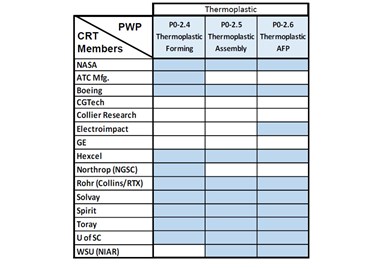
Advanced Composites Consortium (ACC) members and collaborative research team (CRT) assignments for HiCAM’s TPC work packages. Photo Credit: slide 6, “HiCAM Commercial Transport Needs” by Dr. Rick Young, NASA, March 2022.
HiCAM is executed by the ACC, which includes universities and companies from industry. Multiple TPC work packages have been awarded to collaborative research teams (CRT) formed by ACC members. As can be seen in the table at right, Collins Aerospace — listed as Rohr (Collins/RTX) — is involved in all three of HiCAM’s TPC work packages. In addition, Van Tooren leads the project’s welding team, which includes most of the companies in the TPC work packages. This team has developed a preliminary roadmap for certification of welded TPC structures. “We are working on a 2-phase approval,” explains Van Tooren. “The first phase, which is now complete, entailed making a lot of welded coupons using different materials and welding techniques and then testing these. The goal was to show that the material of the welded joint is the same as what you get with co-consolidation — essentially verifying that welding is not bonding.”
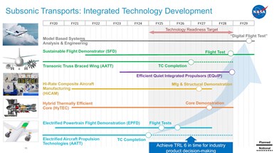
HiCAM demonstrators to be completed before 2027. Photo Credit: slide 11, “NASA ARMD Overview” by Cliff Brown, NASA, presented at FAA Cleen III Spring Meeting, May 2, 2023.
“In the second phase,” Van Tooren continues, “we are working to scale up the testing and in parallel, show structural analysis and design that enables a full-size demonstrator fuselage section or wingbox, or both, to be built. This second phase deals with maturing the manufacturing and supporting technology required to actually build large welded TPC structures. We are using welding as a joining method that can go into next-gen aircraft. So, we are moving up from coupons to large panel and sub-element testing and then to these large demonstrators. The larger coupon and panel testing is scheduled to be completed by the end of 2024 and the full-scale demonstrator(s) are to be built by the end of 2026.”
A preliminary certification roadmap has been completed and is now being reviewed by Boeing. The FAA is also involved in HiCAM through a review panel and well-known players in composites are part of that panel, including Larry Ilcewicz, long-time composites expert at the FAA who worked to explore an all-composite fuselage at Boeing as part of the NASA-led Advanced Technology Composite Aircraft Structures (ATCAS) program. Ilcewicz was also involved in the FAA certification of the Boeing 787, which used a composite fuselage and wings.
Resistance welding issues, special case for certification
Within the certification roadmap being developed by HiCAM, Van Tooren notes that resistance welding is not included with the other welding techniques. “This is because it adds a metal mesh or other resistive element in the weld line that is dissimilar from the substrates,” he explains. “The HiCAM welding group has made the statement that welding is co-consolidation. But that definition is no longer true if you add anything that is not exactly the same as what is in the two parts being joined. In this situation, it then becomes a non-standard method of welding and must be treated differently.”
This may seem odd because resistance welded structures have been certified and flying on the A330/A340 and A380 aircraft for years. Van Tooren explains the rationale: “The area at the interface is where load transfer takes place. If you put a metal mesh there, then you have welding to the matrix only in the openings of the mesh — because that's where you have the normal contact of polymer to polymer. But the rest of the load transfer must go through the metal, which means the metal must now bond to the thermoplastic. So, this type of resistance weld has a bonding aspect to it and cannot be considered a pure weld.”
But what if the resistive element is a carbon fiber mesh? “That mesh must have the same materials and composition as the baseline materials that you connect,” says Van Tooren. “If you add anything — nanofibers, nanotubes or other kinds of fibers than what you have in the parts being welded — then it's no longer like co-consolidation. Instead, you have done something different, where all the loads must transfer through that special material, and thus must be treated as a special case that is not standard welding. Even if you use the same polymer and the same carbon fibers but they are arranged in a different format from the two parts you’re welding, then it still requires special treatment for certification.”
“This is why we as an industry must be careful in our discussions about welding and our definition of welding,” he warns. “Before we make broad conclusions about failures in TPC welding and how this should be addressed in certification, we need to make sure that the welding we are discussing is indeed welding and not this special case of resistance welding or some other technique that introduces new materials and/or new mechanisms in the weld line.”
Offringa comments that not all resistance welding must be considered separately from other welding techniques such as induction welding. “In the case where the same carbon fiber UD prepreg tape in the parts being welded is also the resistance element, with a polymer foil as isolator that is the same polymer as in the UD tape, then no dissimilar material is added to the joint and you have a weld as well.”
Certification of new materials, welding technologies
If Airbus and Gulfstream have already certified TPC welded structures, then why is this certification roadmap still necessary? Van Tooren explains that there has been an evolution in technology, with the latest advances demonstrated, but not yet certified. “The resistance welded J-nose parts were secondary structure, basically a set of fairings, made from glass fabric-reinforced PPS,” he says, noting that PPS allows welding at relatively low temperatures.
“For primary structures, the industry is using induction welding of carbon fabric-based PPS which allows using the carbon fiber-reinforced parts as the susceptor,” says Van Tooren. “This eliminates the need for a resistance element or separate susceptor element and makes the joint a true weld that is much easier to certify. Again, the PPS allows relatively low process temperatures, while the fabric makes induction heating relatively homogeneous.”
He contends that what Collins Aerospace is doing with its welded TPC fan cowl presents many more challenges. “We are not using fabric, but instead UD [unidirectional] tape and higher process temperature materials to enable parts with higher temperature resistance (such as nacelles). We are also welding along the full width and length of the part which is a double-curved structure with much higher curvature than seen in control surfaces. Such structures have yet to be certified.”
Why all these changes? “Using UD tape allows for automated layup (AFP, ATL) and also reduced weight, but these laminates are much more difficult to heat up in a homogeneous manner using induction. Tapes needed to be improved to have a much more uniform resin-to-fiber distribution over the cross-section. Even then, the use of tape comes with much more distinct end effects and hot spots away from the actual weld area. Larger, double-curved parts are much stiffer, and more effort is needed for intimate contact. The use of higher melting temperature polymers also creates challenges in tooling and bladder materials as well as temperature gradients in the parts during welding that creates risk for distortions and residual stresses.”
Industry path forward
In the 2022 CW article on welding process control, Waruna Seneviratne, director of the Advanced Technologies Lab for Aerospace Systems (ATLAS) at NIAR asserted, “As a community, we need to establish weld process qualification protocols and the means of compliance to ensure safe operation throughout the design life of the joint.”
Projects past and present toward certification of welded TPC structures. Photo Credit: CW articles (top, clockwise) EU roadmap for future airframes, Plant tour: Daher Shap’in TechCenter, Collins TPC nacelle structures.
That is indeed what the welding team within HiCAM is trying to achieve. But it is also what the global TPC welding community, mostly in Europe, has been working toward for decades. Indeed, HiCAM is just one of many past and ongoing projects to mature the technology readiness level (TRL) of welded TPC structures and the ability to certify them for future airframes:
- TAPAS1, TAPAS2
- Clean Sky’s GRA and OUTCOME
- Clean Sky 2’s KEELBEMAN and Multifunctional Fuselage Demonstrator (MFFD) including the STUNNING and MECATESTERS subprojects
- CORAC’s Arches Box TP, Composite Aircraft of the Future, ECHOS and TRAMPOLINE
- Germany’s LuFoV-3 TB-Rumpf
- The TPRC’s ENLIGHTEN
- Daher’s EcoProp project with Airbus and second full-scale welded torsion box for EASA CS-25 large aircraft certification
- and additional developments by Aernnova, CETMA, Collins Aerospace/Raytheon/RTX, FACC, GKN Fokker, IS Groupe, KVE Composites/Daher, NIAR and Qarbon Aerospace (see “Thermoplastic composites welding advances”).
“We at Collins are working on this too with HiCAM and other industry projects but also in-house as a global team with DTC in the Netherlands,” says Van Tooren. “We have had to work on so many aspects of the process chain and all of the details behind the shiny demonstrator parts that aren’t often seen. This includes materials, heating, tooling, ensuring the alignment and intimate contact of the welded parts and precisely controlling melting and reconsolidation as well as NDT of the finished welded structures. The demonstrators are important, but how do you develop a part that can actually be put into service and then manufacture it on an industrial scale, not just for R&D? We have developed a process chain that will not only support our goal to demonstrate a welded TPC fan cowl but to put that part into flight test and eventually into serial production on one our nacelle products. And working with the industry on certification is a key piece of that program.”
“Our goal is to work with OEMs, Tier suppliers and the aviation authorities to define the TPC welding process,” says Unger at Toray, “and also its path to certification so that this technology can enable unitized thermoplastic assemblies for more efficient, next generation airframes.”
Related Content
MFFD thermoplastic floor beams — OOA consolidation for next-gen TPC aerostructures
GKN Fokker and Mikrosam develop AFP for the Multifunctional Fuselage Demonstrator’s floor beams and OOA consolidation of 6-meter spars for TPC rudders, elevators and tails.
Read MoreManufacturing the MFFD thermoplastic composite fuselage
Demonstrator’s upper, lower shells and assembly prove materials and new processes for lighter, cheaper and more sustainable high-rate future aircraft.
Read MoreJEC World 2024 highlights: Thermoplastic composites, CMC and novel processes
CW senior technical editor Ginger Gardiner discusses some of the developments and demonstrators shown at the industry’s largest composites exhibition and conference.
Read MoreComposites end markets: Electronics (2024)
Increasingly, prototype and production-ready smart devices featuring thermoplastic composite cases and other components provide lightweight, optimized sustainable alternatives to metal.
Read MoreRead Next
All-recycled, needle-punched nonwoven CFRP slashes carbon footprint of Formula 2 seat
Dallara and Tenowo collaborate to produce a race-ready Formula 2 seat using recycled carbon fiber, reducing CO2 emissions by 97.5% compared to virgin materials.
Read More“Structured air” TPS safeguards composite structures
Powered by an 85% air/15% pure polyimide aerogel, Blueshift’s novel material system protects structures during transient thermal events from -200°C to beyond 2400°C for rockets, battery boxes and more.
Read MoreDeveloping bonded composite repair for ships, offshore units
Bureau Veritas and industry partners issue guidelines and pave the way for certification via StrengthBond Offshore project.
Read More


