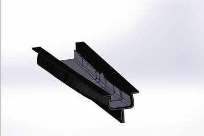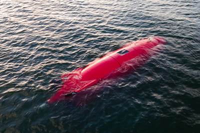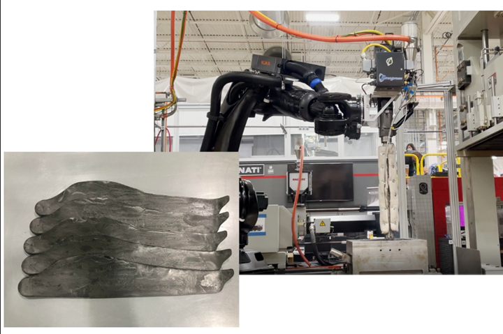
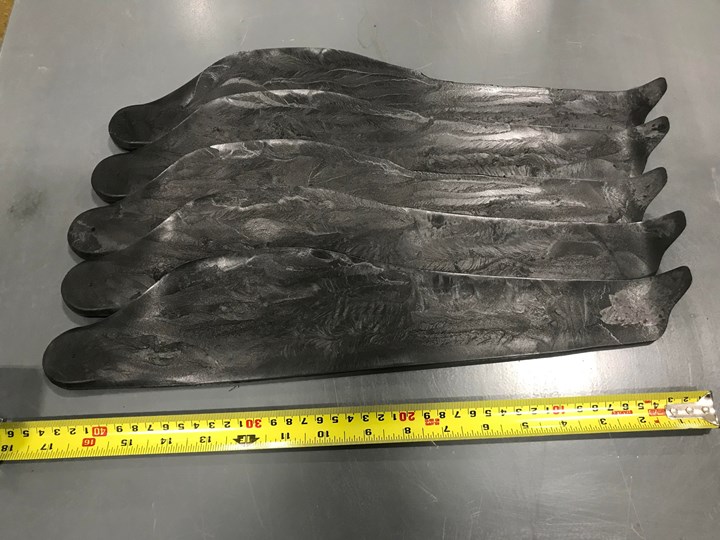
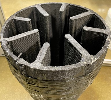
Large-scale composite 3D printing + compression molding. Aiming to enable high-performance, high-volume, large-scale, 3D-printed composite parts, Oak Ridge National Laboratory (ORNL) has developed a system called AMCM to combine robotic, extrusion-based 3D printing with compression molding. First test cases include the propeller blades pictured, with goals to include automotive battery boxes and other high-volume, complex-geometry applications. Photo Credit: ORNL (left) and CW (right)
The 110,000-square-foot Manufacturing Demonstration Facility (MDF) at Oak Ridge National Laboratory (ORNL, Oak Ridge, Tenn., U.S.) is a U.S. Department of Energy (DOE) user facility focused on early-stage research and development in many areas of manufacturing, robotics and simulation — including composites.
One innovation CW has frequently covered is ORNL’s Big Area Additive Manufacturing (BAAM) large-format 3D printer, developed and commercialized with Cincinnati Inc. (Harrison, Ohio, U.S.). BAAM has been used to fabricate molds for infrastructure, aerospace and automotive applications, and end-use parts ranging from machine tool bases to marine structures and more.
One limitation of large-format additive manufacturing (AM) historically has been that 3D printing tends to produce parts with irregular and rough surfaces as well as relatively high void content, which prohibits use of AM in many high-performance end-use parts. Several commercial efforts have been made to reduce porosity by adding a secondary processing step such as compression molding. Over the last two years, one ORNL team has been working to develop its own scalable, two-step process for eliminating voids in high-volume, large-format end-use parts, while maintaining a short production cycle time of less than 2.5 minutes per part.
Developing a cell for large-scale, high-volume, 3D-printed parts
ORNL’s process, called AMCM (additive manufacturing and compression molding), combines a robotic-based extrusion printer with an immediate compression molding step.
AMCM has been in development for more than two years, and the team originally began by using the MDF’s existing large-format BAAM printer and compression press. Using this setup, ORNL was able to demonstrate initial benefits to the process combination such as low voids in the final part. However, the machines were not next to each other, and the relatively short distance of travel between the BAAM and press required an additional reheating step in a belt oven prior to compression molding to soften the preform again to the correct glass transition temperature (Tg). These five to six extra minutes of preheating per part significantly increased the overall cycle time up to eight to nine total minutes per part, says Dr. Vipin Kumar, R&D associate staff member in ORNL’s Advanced Composites Manufacturing group.
It quickly became apparent that a dedicated production cell that combines AM and compression molding into one system would be needed to demonstrate that this technology could be used in a high-volume production environment, Kumar notes.
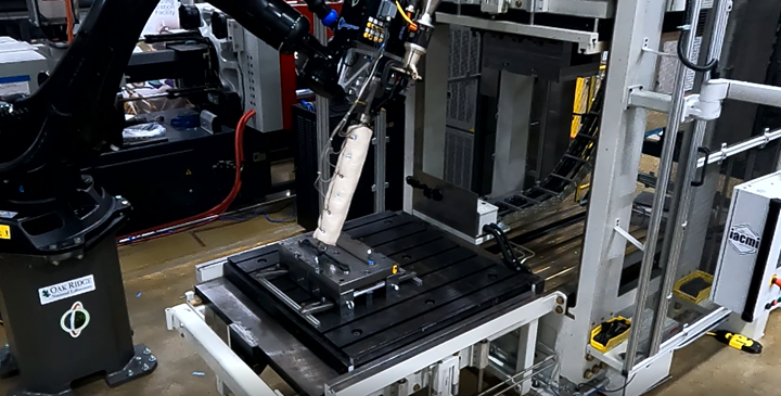
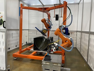
Lab-scale test cell. Set up in fall 2021, ORNL’s lab-scale AMCM cell combines robotic, extrusion-based 3D printing and a compression press to test the limits of the system. Ultimately, ORNL is working with industry partners to produce commercial-ready applications in aerospace, automotive and other industries. Photo Credit: ORNL
To improve the cycle times of the technology, ORNL came up with the concept for the current AMCM cell, which was installed in November 2021. The cell includes a Strangpresse (Youngstown, Ohio, U.S.) extrusion printhead on a six-axis KUKA (Augsburg, Germany) robot arm, a Trinks (De Pere, Wis., U.S.) 500-ton compression press and a material dryer system. The printer can deposit up to 150 pounds of material per hour.
“We extrude the material at the normal melting temperature of the material (sometimes we extrude at a little higher temperature as well) which gives us enough time before the material cools down below its Tg (main parameter to get any compression on the material),” says Kumar. “Worth noting, is that all these parameters change when we use a heated mold. In that case, we do not have to worry about getting the material to cool down fast. But the addition of the heating step will increase the part cycle time.”
Printing into the mold. To reduce cycle times, the AMCM system prints directly into the mold that will travel, via conveyor belt, into the press. Photo Credit: ORNL
To produce a part in the AMCM cell, the part geometry is extruded directly onto a mold, resulting in a 3D tailored preform that travels via conveyor belt directly into the press for immediate molding (see video below). Kumar explains that the material is extruded at, or a little above, the melting temperature of the material, and that the design of the AMCM cell allows the preform to reach the press for compression before the material has cooled down below its Tg.
During a recent tour of the MDF, CW watched Kumar and his colleagues demonstrate the AMCM cell on a simple, flat panel of 20% carbon fiber/ABS, which was printed, pressed and dried in a total cycle time of 2.5 minutes. Since then, the AMCM has also been demonstrated on additional planar parts such as drone propellers.
The idea is that the robotic arm-based printer could produce parts of relatively large size or complex geometry; however, the current lab-scale system is limited to the 41- x 48-inch mold size limit of the 500-ton press. Kumar notes that, currently, the molds are not heated, but, if larger parts were to be printed, heated molds may be needed to ensure the 3D-printed preform does not cool down too fast and remains above its Tg through the printing process and transfer into the press. “It is worth noting that current parameters such as temperature for extrusion change when we use a heated mold,” he says. “In that case, we do not have to worry about getting the material to cool down fast, but the addition of the heating step will increase the part cycle time.”
Kumar explains that the first demonstrations of the cell have focused on planar, one-material parts to test the speed and capabilities of the system, but ultimately the team is aiming for more complex, non-planar shapes and multi-material prints — with materials including glass fiber-reinforced ABS, nylon and others. Projects with industry partners are also in development.
What are the benefits? According to Kumar, compared to traditional injection molding or extrusion compression molding (ECM) processes, this method is said to produce parts with porosity of less than 1.5%, with about 80% of the fibers aligned in the deposition direction (see this paper ORNL published on the process for more information). “We’re combining the fiber control of additive manufacturing, where the fiber follows the bead direction, with the low porosity of compression molding,” says Kumar.
“This is a highly controlled process, removing essentially all voids, resulting in focused fiber orientation and alignment,” adds Dr. Ahmed Hassen, staff scientist at ORNL.
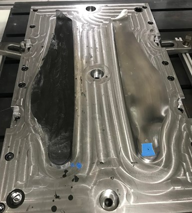
First test case: UAV propeller blades. ORNL envisions its AMCM cell as being capable of producing high-volume commercial parts, potentially at large scales. As a first test case, technicians built a series of carbon fiber-reinforced thermoplastic propeller blades like those on unmanned aerial vehicles (UAV). Photo Credit: ORNL
The AMCM cell, though existing at the MDF as a lab-scale system, is said to be easily scalable for a production setting, and enables digitization, digital design and automation.
Kumar and his team envision this process enabling high volumes for next-generation composite components in fields like automotive (such as battery boxes or seatbacks) and urban air mobility (such as drone propellers). The system is projected to produce up to 120 parts per hour when fully optimized, Kumar says.
More in 3D printing
The AMCM process was one of the main features of CW’s most recent MDF tour, but not the only composites 3D printing innovation under development. 3D printing, in general, continues to be a large focus area for ORNL, including ongoing work with its BAAM printer to include multi-material printing; printing with foams; printing with bio-based, recycled fiber, or natural fibers; printing wires into the center of 3D-printed parts; and more.
Down the aisle from the MDF BAAM printer sits the first laboratory version of the Reactive Additive Manufacturing (RAM) printer. Developed with Magnum Venus Products (MVP, Knoxville, Tenn., U.S.) and using Polynt (Durham, N.C., U.S.) resins, this is a large-format thermoset composite 3D printer that is also being developed and sold in commercial form at MVP’s nearby Knoxville facility.
Filament winding as reinforcement for 3D printing. Using MVP equipment, ORNL researchers explore combination of filament winding (for compressive strength) over top of a 3D-printed part (to enable complex geometry). Photo Credit: CW
At the MDF, ORNL continues to optimize material flow characteristics and build demonstrator parts using the RAM system. Additional work with the RAM includes a project with MVP to integrate the RAM system with an MVP lab-scale filament winder, also located within the MDF. This work involves printing demonstrator parts using the RAM printer, followed by filament winding additional material around the cured, 3D-printed part as a reinforcement. ORNL is also working on a project with Boeing (Chicago, Ill., U.S.) to 3D print tooling using the RAM system.
New 3D printing materials development. Orbital Composites partners with ORNL in the development of new thermoset and thermoplastic materials for use with its robotic 3D printing systems. Several test machines are set up at the MDF. Photo Credit: CW
ORNL is also pursuing optimization of multi-material robotic 3D printing, working with partner Orbital Composites (San Jose, Calif., U.S.). Researchers are working on enabling the system — capable of printing thermoplastic or thermoset filaments — to more accurately print on top of non-planar surfaces and to print continuous fibers on top of thermoplastic discontinuous fiber parts. ORNL is working on material chemistry while Orbital aims to perfect the machine and accompanying software. Applications under development include drone components, tooling and automotive and wind parts.
Continuing composites innovation: CMC, biomaterials and more
With and without 3D printing, the MDF is currently active in many composites areas, including carbon-carbon (C-C) materials for extreme environments like space re-entry structures and nuclear reactors. For example, Orbital Composites, via ORNL’s MDF, is attempting to 3D print C-C rocket nozzles. ORNL is also working on C-C tooling — beneficial because it has near-zero thermal expansion. Another collaboration with project partner, Sandia National Laboratory (Albuquerque, N.M., U.S.), focuses on C-C and ceramic matrix composite (CMC) applications for a variety of defense and aerospace applications.
Bio-based materials development is also a key focus area, especially bio-based feedstock for 3D printing, led by Dr. Soydan Ozcan, ORNL senior R&D scientist. ORNL partners closely with the University of Maine Advanced Structures and Composites Center (UMaine, Orono, Maine, U.S.) on the development of cellulose nanofibrils (CNF) and applications of these materials using a variety of manufacturing processes. In one pilot project with UMaine, two molds for seven-piece, 100-foot offshore wind blades were built on UMaine’s 60- x 22-foot build volume LFAM printer using CNF materials. Within this project, ORNL completed the materials and equipment development.
Another team, focused on sustainability, is workng on lab-scale recycling methods for composite components including wind blades. The system here employs a shredder and waterjet cutter to explore new ways of processing/shredding end-of-life (EOL) parts. Reuse cases are also being evaluated, such as incorporating recycled chopped material into 3D printing pellets to feed back into the BAAM printer.
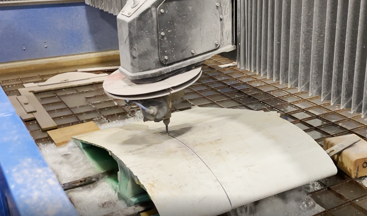
Focus on EOL and sustainability. ORNL work on end-of-life (EOL) solutions includes waterjet cutting of wind blades (pictured), followed by shredding and reuse via 3D printing or other processes. Photo Credit: CW
A thirty-minute drive from the MDF, DOE’s Carbon Fiber Technology Facility (CFTF) at ORNL runs a full-scale carbon fiber production line, enabling technicians to experiment and optimize various aspects of carbon fiber production and properties of the carbon fibers coming off the line. A BAAM printer and pultrusion system located at the CFTF facility enable immediate parts fabrication from the newly made fibers. Ongoing efforts include work to make low-cost, high-quality carbon fiber from coal, and carbon fiber that is treated during production in such a way that makes it inherently resistant to lightning strikes — negating the need for additional lightning strike protection (LSP) for aircraft or wind turbine parts.
According to Dr. Vlastimil Kunc, group leader for Advanced Composites Manufacturing at ORNL, CW’s tour barely scratched the surface of the work that ORNL and its partners continue to do at the MDF. “Many of tomorrow’s innovations are getting their start here today,” he says.
Related Content
Bio-inspired EV underbody panel developed by TPI Composites, Helicoid Industries
Composite underbody panel for battery pack protection, made of stacked multiaxial noncrimp fabric, will serve high-volume commercial and automotive markets.
Read MoreLarge-format 3D printing enables toolless, rapid production for AUVs
Dive Technologies started by 3D printing prototypes of its composite autonomous underwater vehicles, but AM became the solution for customizable, toolless production.
Read MoreHow AI is improving composites operations and factory sustainability
Workforce pain points and various logistical challenges are putting operations resilience and flexibility to the test, but Industry 4.0 advancements could be the key to composites manufacturers’ transformation.
Read MorePlant tour: Middle River Aerostructure Systems, Baltimore, Md., U.S.
The historic Martin Aircraft factory is advancing digitized automation for more sustainable production of composite aerostructures.
Read MoreRead Next
Composites speed concrete facade fabrication
The 45-story One South First building, on the 11-acre Domino Park campus in Brooklyn, N.Y., features a geometrically complex concrete facade made, in part, with composite molds fabricated using large-format additive manufacturing.
Read MoreHybrid, large-format additive tooling: Lighter, faster, less costly molds for big parts
Additively manufactured cores, CFRP face skins produce large tools for prototype, low-volume aerostructure parts.
Read MoreLarge-format 3D printing enables toolless, rapid production for AUVs
Dive Technologies started by 3D printing prototypes of its composite autonomous underwater vehicles, but AM became the solution for customizable, toolless production.
Read More

.jpg;width=70;height=70;mode=crop)




.jpg;maxWidth=300;quality=90)


