
Modular design eases big wind blade build
First segmented composite blade increases power generation, eases installation and keeps weight and costs in check.

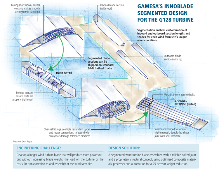
Gamesa's INNOBLADE Segmented Design for the G128 Turbine Illustration: Karl Reque
Today’s larger wind turbine rotors are pushing the limits of transportabllity to wind farm sites. Source: Gamesa
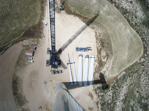
Gamesa’s modular blade technology enables affordable transport and installation of high productivity rotors, even in remote locations. Here, blade segments delivered to a wind farm await assembly. Source: Gamesa

Metallic fittings are bonded into the spar laminate of each blade segment and then bolted together to join the two segments. Source: Gamesa
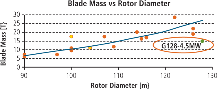
Fig. 1: The G128 rotor defeats the square-cube law — power is proportional to the square of the rotor diameter while wind blade mass increases with the diameter cubed — reducing average weight by 25 percent for a rotor that has a diameter greater than 100m/328 ft. Source: Gamesa


Engineering challenge:
Develop a longer wind turbine blade that will produce more power output without increasing blade weight, the load on the turbine or the costs for transportation to and assembly at the wind farm site.


Design solution:
A segmented wind turbine blade assembled with a reliable bolted joint and a proprietary structural concept, using optimized composite materials, processes and automation for a 25 percent weight reduction.
The primary drivers in wind turbine development are power generation and cost. Assuming no changes in design, materials or construction methods, the amount of generated power increases with blade length in proportion to the square of the turbine rotor’s diameter, but blade mass increases in proportion to the cube of its diameter. This means the rate of mass increase exceeds the rate of generated power increase as blades get longer. As a result, longer, exponentially heavier blades vastly increase transportation and installation difficulties and cascade mass and cost increases throughout the turbine/tower system.
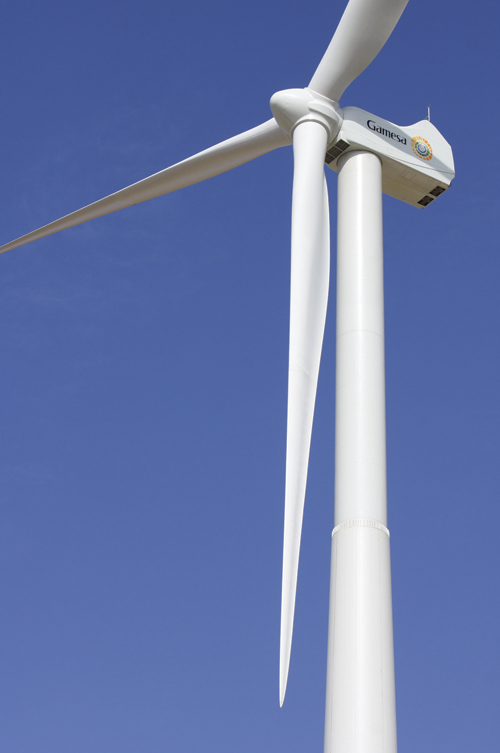
That’s why Gamesa’s (Vizcaya, Spain) G128 turbine, fitted with the world’s first commercial segmented composite blade, is making big news. Based on Gamesa’s trademarked INNOBLADE design, the blade is the longest on the market for onshore turbines (62.5m/205 ft). The turbine generates up to 5 MW of power, but its blades weigh less than blades now used on standard 100m/328-ft rotors and are as easy to install as the much shorter blades used on 2-MW systems.
A long process
Gamesa patented a segmented wind blade design in 2005. It was refined to increase annual energy production and reduce noise and cost, in part through participation in UpWind, a European Union-funded 6th Framework Program that explored large-turbine design solutions from 2006 to 2011. A 42.5m/139-ft in-house blade design was evaluated with different aerodynamic profiles for efficient energy production, including aeroelastic analysis. Gamesa developed a trade-off matrix for various blade joint alternatives, studied their effects on modal shapes and pursued integration of a control system that would mitigate the increased load of longer blades (see “Big blades, big innovations,” under "Editor's Picks," at top right).
In parallel to UpWind, more than 150 Gamesa engineers completed the majority of the G128 turbine development in-house, obtaining multiple patents for the innovations required. “We had a strict limit on weight and aerodynamic performance, so we had to develop a joint without modifying the blade aerodynamics,” says blade chief engineer Ion Arocena. “This forced us to invent new technologies.” Starting with an optimized geometry supplied by Gamesa’s aerodynamics department, the team began prototyping a composite blade structure. “We then supplied comments back to the aerodynamics group on what best fit our structural and manufacturing needs,” says Arocena.
Segmenting the blade
After several iterations between the aerodynamics and structural teams, Gamesa tackled where to divide the blade. UpWind research indicated that a wide range of joint positions were possible without disturbing the blade’s modal shapes and natural frequencies. “We could have separated the blade anywhere,” Arocena points out, but they chose at that time to “locate the joint in almost the middle of the blade to minimize the length for transport.” This original concept has since evolved into a modular system that features inboard (root) sections and outboard (tip) sections in customized lengths to suit the specific wind conditions of each installation (see drawing).
“It is possible to ship these blades using two standard 90-ft [27.4m] flatbeds,” Arocena says. “For a standard 100m rotor, you need blade-specific trucks, which are much more expensive.” For larger rotors, many ships, trucks and shipping terminals are unable to handle the blades at all. “Rotors with a 117m [384-ft] diameter are pushing the limits for transporting the equipment to the wind farm,” he says. “Gamesa’s INNOBLADE design offers the ability to install high-productivity rotors in remote locations.”
Bonded fittings and bolted assembly
With the basic configuration in hand, Gamesa still faced much work to establish exactly how the joint would be manufactured and then assembled after delivery to the wind farm site. “When the blade is in operation, it has to look and act as a one-piece blade, with a continuous bend and no flat spot, in order to avoid disrupting the aerodynamics and loading,” explains Daniel Broderick, Gamesa’s resident engineering manager for North America. “The systems we developed allowed for a significant mass in the middle of the blade yet the wind turbine does not feel that it has a modular blade. In fact, that is a unique design benefit of the G128 turbine: It can use either the INNOBLADE or a one-piece blade.”
UpWind blade findings had indicated that channel fittings outperformed spar lugs or T-bolts for the blade joint. These channel fittings were bonded to a pultruded carbon fiber-reinforced profile embedded within the spar cap laminates, which widened at the joint to accommodate multiple fittings. A simple bolted joint between each set of two fittings connected the two blade segments.
“The final G128 design uses many insert and bolt connections within the joint,” says Arocena. “We designed this joint according to aircraft industry regulations for fail-safe performance and damage tolerance. Thus, if any inserts fail, the rest must work. There are close to 15 connections in the upper section of the joint and the same number in the lower section.”
The inserts are metallic and are bonded into the blade laminate in such a way that they form a double lap-shear joint, long considered by the aerospace industry to be one of the strongest options for adhesively bonded joints in composite structures. “The bonded metallic inserts enable the two segments to be bolted together, with all of the loads in the blade transferred through the joint,” says Arocena. “It is very critical that the joint functions precisely, so we did not want to use a manual process for assembly. We decided the best way to ensure a quality and robust process was to use automation for the manufacture and installation of the inserts.” Arocena explains that the inserts are installed in a cleanroom environment. “Our results show we have maintained a very consistent quality of joint.”
The metal bolts are equipped with preload sensors. “The assembly tool used to make the connections receives input from the sensors so that when the correct load is reached, the tool stops,” Arocena explains. According to one supplier of preload sensors, the previous method of measuring bolt load, with a torque wrench, was accurate to within 20 percent, at best. With sensors, the accuracy can be maintained within 1 percent. “Thus, 100 percent of the blades are properly assembled,” says Arocena. The maximum blade assembly time is four hours.
After the bolts are secured, a metallic external fairing covers and protects the joint’s metal components and provides a smooth transition across the joint. Gamesa claims its joint and assembly design achieves low cost by enabling transport via standard equipment used for 2-MW turbines. The joint adds ~10 percent to blade cost, but the increase is more than offset by transport savings.
Balancing materials and processes
“This is not a complex joint design,” says Arocena of the G128 blade, “but small parameters could greatly affect the load capability, and we needed a high load-carrying capacity.” The materials used in blade manufacturing normally withstand much lower loads than those seen in the G128’s joint. “We had a wide selection of materials to consider, both metallic and composite laminate. The solution we chose uses prepreg in the spar laminate of the joint area to attain that load capacity.” Some designs worked perfectly as a joint but were too expensive to produce. Others that were affordable but did not carry enough load. “In the end, we found the right balance,” says Arocena.
The G128 uses both glass and carbon fiber, balsa core and a proprietary new multipanel internal structural concept to optimize the weight allocation inside the blade. Arocena observes, “A complete set of blades for a rotor over 100m in diameter averages 20 metric tonnes [44,092 lb] per blade. Our combination of load reduction and internal structure optimization reduces this by 25 percent to 15 metric tonnes [33,069 lb]” (see Fig. 1, bottom left). “We considered many different materials, including plastic foams and balsa cores, and we also combined different processes, such as resin infusion, prepreg and pultrusion. We strategically used each material and process to be cost-effective and to minimize weight.”
Although automation could reduce blade manufacturing cost, Arocena notes that “it also has the potential to increase costs. We have studied this for some time and have chosen to use automation only where it provides a demonstrable advantage.”
Future positioned
Gamesa completed an extensive validation program for the G128 turbine — more than 600 component tests at 100 certified laboratories in the U.S., Japan and Europe, 190 functional tests at the Wind Turbine Test Laboratory (LEA, Navarra, Spain) and more than 300,000 hours of validation and test engineering. Twenty-seven segmented blades are now in service on nine Gamesa 4.5-MW G128 turbines and many more projects are in progress.


.jpg;maxWidth=300;quality=90;format=webp)


Related Content

Polar Technology develops innovative solutions for hydrogen storage
Conformable “Hydrogen in a Box” prototype for compressed gas storage has been tested to 350 and 700 bar, liquid hydrogen storage is being evaluated.
Read More
Honda begins production of 2025 CR-V e:FCEV with Type 4 hydrogen tanks in U.S.
Model includes new technologies produced at Performance Manufacturing Center (PMC) in Marysville, Ohio, which is part of Honda hydrogen business strategy that includes Class 8 trucks.
Read More
Recycling end-of-life composite parts: New methods, markets
From infrastructure solutions to consumer products, Polish recycler Anmet and Netherlands-based researchers are developing new methods for repurposing wind turbine blades and other composite parts.
Read More
JEC World 2023 highlights: Recyclable resins, renewable energy solutions, award-winning automotive
CW technical editor Hannah Mason recaps some of the technology on display at JEC World, including natural, bio-based or recyclable materials solutions, innovative automotive and renewable energy components and more.
Read MoreRead Next

“Structured air” TPS safeguards composite structures
Powered by an 85% air/15% pure polyimide aerogel, Blueshift’s novel material system protects structures during transient thermal events from -200°C to beyond 2400°C for rockets, battery boxes and more.
Read More
Developing bonded composite repair for ships, offshore units
Bureau Veritas and industry partners issue guidelines and pave the way for certification via StrengthBond Offshore project.
Read More