Reducing manufacturing cost via RTM
Airbus Bremen aims to replace dozens of prepreg components and assembly operations with a unitized multispar composite flap molded in a one-shot process.
The goal of the Composite Multispar Flap (CMF) project, led by Airbus Bremen (Bremen, Germany), was to simplify production of the complex 7.4m-long outboard wing flaps for narrowbody commercial aircraft. Airbus Bremen is responsible for the design and manufacture of flaps, spoilers and other high-lift systems — movable wing parts that optimize take-off and landing. The CMF project was funded in 2005, and a multifunctional team, led by Airbus engineer Dr. York Roth, began design studies and feasibility tests in close cooperation with partners Radius Engineering (Salt Lake City, UT, US) and Faserinstitut Bremen (FIBRE, Bremen, Germany).
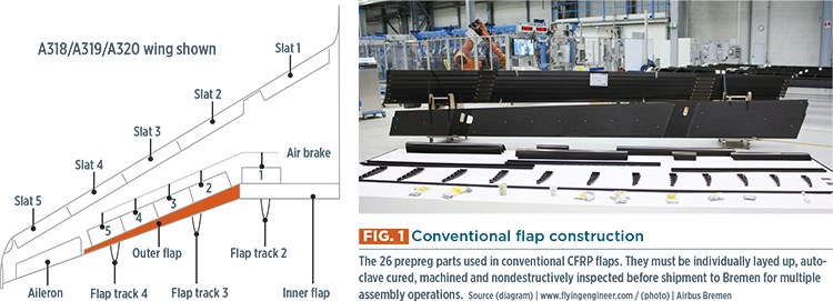
This team targeted the A320 outboard flap, comprising 26 separate carbon fiber-reinforced polymer (CFRP) components in the current production version, including two skins, nose elements and multiple ribs and spars. All of these prepreg parts must be individually layed up, autoclave cured, machined and nondestructively inspected before shipment to Bremen for an equally intensive assembly process (see Fig. 1, at left). The metal end ribs and load frame — the latter enables attachment and load transfer to the wing — must be mounted in an assembly jig, followed by ribs and skin-stringer panels. Technicians drill holes for rivets, and then take the composite and aluminum elements apart, deburr and clean debris from the drilled holes and replace all components into the jig. Multiple drilling and riveting steps follow, after which the CFRP leading edge and metallic trailing edge components are manually installed.
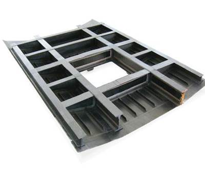
The CMF alternative was conceived as a multispar torsion box that integrates all 26 prepreg parts, including the leading edge, into a unitized structure made using out-of-autoclave resin transfer molding (RTM) technology. “CMF would not only eliminate a significant number of assembly operations,” says Airbus Bremen’s industrial moveable architect Dr. Stefan Bauer, “but also the high lead times and complex process chain for each of the many prepreg components.”
The challenge would be how to design the part and manufacture this now closed structure via single-shot injection and cure with acceptable porosity, while maintaining current program tolerances. “The final geometry must be precise due to the need for mating the load frame with flap tracks for attachment to the wing, as well as to meet aerodynamic requirements,” explains fellow Airbus Bremen manufacturing engineer, Mohamed Attia. Because the potential cost savings exceeded 20% without adding weight to the entire painted and equipped flap, Airbus Bremen embraced the challenge.
Refining the design
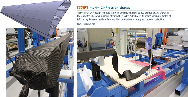
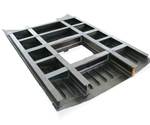
“The original idea,” Bauer recalls, “was to replace all of the prepreg stringers and ribs with four to five braided boxes, followed by upper and lower skins.” (See Fig. 2, at left.) These dry carbon fiber preforms would be laid into the RTM mold and then injected with epoxy resin to form the final integrated, cured part.
“One of the main challenges was that the part is over 7m long,” Bauer notes. “We had not worked with RTM on that large of a scale before. However, Radius Engineering was an excellent partner. We started with small parts and worked our way up
the scale.”
A 1.5m section was built in 2007 and static tested to demonstrate design and process, achieving a technology readiness level (TRL) of 4. By 2010, the idea of braids had been dropped. Bauer explains the braided “socks” used for the flap preforms were made with a constant diameter, but the flap widths weren’t constant. Instead, they were highly tapered, and, thus, so also were the box spars. This meant that the ±45° fibers in the braid were optimally oriented only at the braid diameter, which was roughly halfway down the box spar length. At the wide (≈200 mm) and narrow (≈80 mm) ends, the fiber orientation would, in fact, not be ±45°. According to Attia, this less-than-optimum fiber orientation necessitated larger knockdowns in properties, driving up weight to meet stress requirements. “The dry braided fabric skews easily,” he adds, further complicating optimal fiber arrangement.
There also was a need to look at the scalability of the manufacturing process to industrial production rates. With the braided box beams, the original tooling was required early in the process to provide shaping mandrels for the preforms. If “double T” (aka I-beam) spars were used, instead, dummy mandrels could be used for preforming and the RTM mandrels would only be required during the part injection and cure cycle. Given the above factors, the design was changed to I-beam spars, using conventional 5-harness satin fabric.
Manufacturing a full-scale flap
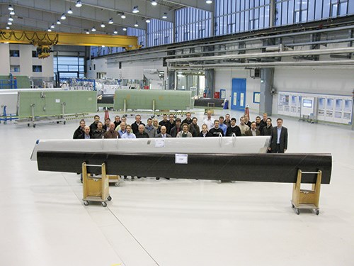
The new I-beam-based design was used to produce a full-size demonstrator in 2010, and ultimately reached TRL 5. Because a rectangle is easier to produce than the actual tapered shape of the flap, this iteration of the CMF was made using 7.8m long aluminum mandrels and RTM molds and was then machined to its final dimensions.
Both the mandrels — which split into three pieces to facilitate removal — and the exterior surface tools required significant engineering. “For thick parts, it is easy to meet thickness tolerances with RTM,” says Bauer. But the CMF is comparatively thin, 2 mm up to 5 mm in reinforced areas. Normally, thin parts such as this are made using prepreg and a vacuum bag, where, as Bauer explains, “You mainly have tolerance effects from the resin content of the raw material and some due to the single tooling side.” But changing the CMF to RTM resulted in the part thickness being fully dependent on two milled tooling surfaces.
“The effect of tooling accuracy on the part thickness was doubled,” notes Bauer, adding, “The tooling had to be very accurate to ensure that the fiber volume content was within design tolerances.” He points out that because the thickness of the part changes the resin content, “in some areas, if you have even less than a 0.2-mm deviation in your tool, you’re already out of tolerance for fiber volume.”
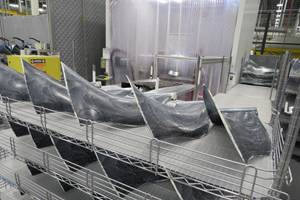
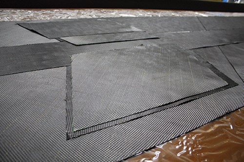
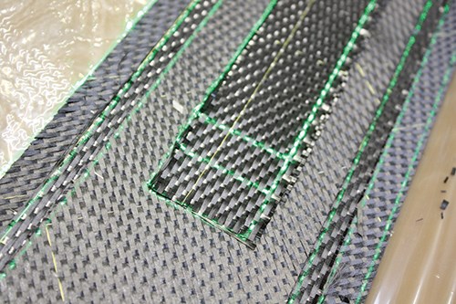
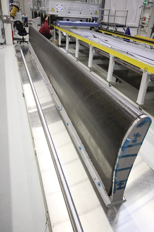
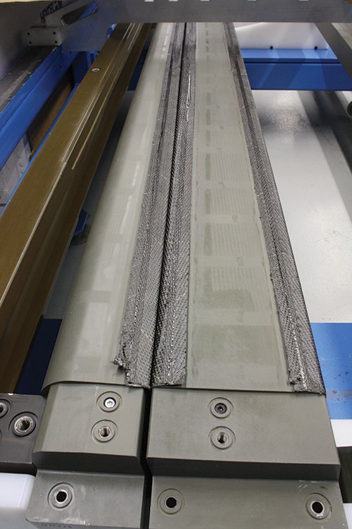
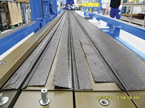
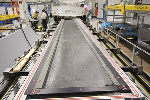
Part production began with fabrication of skin preforms, made by laying dry fabric onto slipsheets using laser projection systems (Steps 1 & 2, at left). The 5-harness satin fabric was made using dry carbon fiber from Hexcel (Stamford, CT, US). The curved skin preform layup, which included bottom skin, leading edge and top skin, was then applied to a flap-shaped fixture, and spar preforms were similarly layed into “double T” mandrels (Steps 3 & 4). A reusable vacuum bag was employed to debulk and shape the preform layups in both cases.
Bauer concedes that there were numerous handling and preforming steps, and that the latter required great attention to accuracy.
“The edge of ply positioning is critical to hitting tolerances,” he notes, “But still, you never knew if the preform was exactly where it should be on the inside of the tool. Was it within tolerance? So we developed an innovative concept plus engineering design to deal with this.”
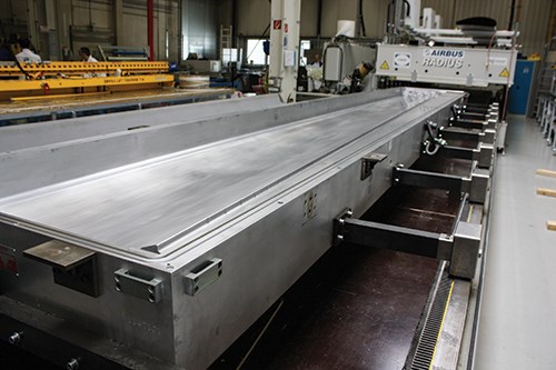
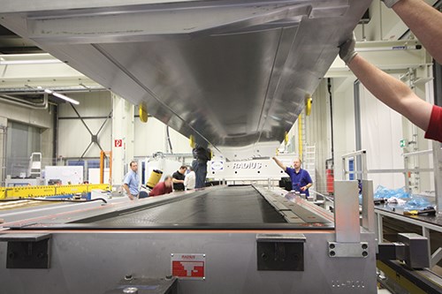
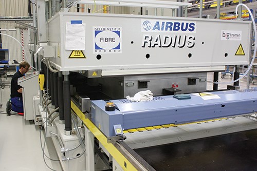
The skin and I-beam spar preforms were then mated and placed into and enclosed in the RTM tool (Steps 5-7), which was designed and built by Radius Engineering. The tool, preforms and resin were preheated to ~100°C, the resin was injected and the composite was then ramped to the cure temperature of 180°C. Hexcel’s HexFlow RTM6 resin was used because it is the main RTM epoxy currently qualified and used for structures at Airbus.
“The part is so complex that we don’t want to have to control the resin flow like with infusion,” says Bauer. The process had to be stable and reliable. Porosity problems were addressed by control of vacuum and pressure. “Of course, the tooling design is important,” he notes, “and temperatures were chosen so that no off-gassing occurs during processing, which could cause porosity.”
It is noteworthy that only one injection point and one outlet were used for such a large part. This is unusual, because the typical setup for many RTM parts employs multiple injection and outlet points. “But the issue with these is that you have to control them,” counters Bauer. “The more points that you have to control, the more risk, due to leaks and flow issues.” He adds that for the CMF, injection happens only at one point but then moves in a line within the tool. “It is a very simple yet robust process,” says Bauer. “It has to be, because if we lose a part it’s not just a rib but an entire 7m long flap.”
After a 2-hour cure cycle, the finished part was demolded hot while still above 100°C, because cooling on the tool causes part-removal issues. The use of aluminum tooling, especially in the reinforced load introduction areas of the part, could result in damage to the undercuts unless it was demolded before the metal could shrink.
A final challenge was that the flap structure is a closed box. That, Bauer explains, presents issues for how to inspect the final structure. The CMF team began working with Bremen-based Thyssen Krupp System Engineering to inspect demolded, unitized parts with a phased array ultrasonic (UT) nondestructive inpsection system that uses one-sided access and a water film as couplant with the part’s surface.
Thyssen Krupp helped develop the inspection technique and patented NDI equipment, which uses spring loading to help focus the phased-array ultrasonic sound waves over the part’s contours and look inside to spars beneath the skins as well as to the radii between the spars and skins. In fact, the system uses two heads — one to travel along the spars and one to inspect the radii between the spars and skins — to speed up and ensure thorough inspection. “We also use different end-effectors to see inside and check these areas in one step,” explains Bauer. The team also addressed how to repair the flap if damaged in service, including inspection, damage removal and repair patch techniques.
A second issue presented by the closed box structure was how to achieve attachment and load transfer to the wing. Previously, a metal load frame and end ribs were used to achieve this. Although the new unitized structure greatly reduces mechanical fasteners, some are still needed for the metal load transfer parts and the metal trailing edge. Attia points out that the CMF’s lower fastener count not only reduces risk of fatigue, “but also fiber damage from machining.” He adds, “Putting holes into highly optimized composite laminates is very inefficient in both design and manufacturing.” That’s one reason a Bremen R&T team continues to push for greater part integration. An alternative design for load attachment points has enabled their integration and transformation from metal to composites, using carbon fiber reinforcements. The initially separate metal trailing edge also has been integrated, converted to a sandwich construction, using Evonik (Essen, Germany) closed-cell foam and carbon fiber skins, layed up and RTM’d with the rest of the CMF.
“The original CMF design was not fully optimized as it could have been within a completely new aircraft design,” explains Attia. “This is because the solution was developed as a retrofit design for the in-service A320 with design restrictions, especially on the load-introduction area.” The team believes it is possible to extend CMF cost savings toward 30% with these integrated CFRP trailing edge and load transfer components.
Ready for industrialization
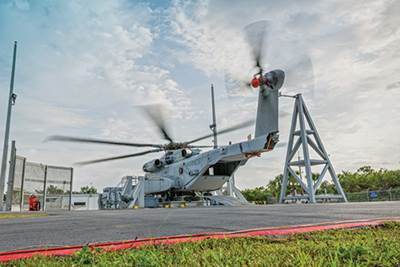
The full-scale demonstrator was a success and was on exhibit at the 2013 JEC Europe show in Paris, France. Bauer cautions that the manufacturing steps, as shown here, are not yet industrialized. Upon implementation, many of them — e.g., fabric layup, debulking, placement of tools into RTM mold — would be automated, using robot. (Read more online about automating layup and debulking of complex composite structures by clicking on “Automating the CH-53K’s composite flexbeams” under "Editor's Picks" at top right).
When the process is put into production, will there be potential issues with bonding when so many previously separate components are co-cured together in a single RTM cycle? Bauer says no. “This issue with delamination is typical of prepreg,” he says. “With RTM, the issue is porosity.” As is typical with most aerospace structures, porosity in composite wing flaps must be less than 1%. For the CMF, Bauer says the risks lie in the part’s large expanse and in the potential for porosity in the radius between the skin and spar. “We have achieved good quality in the laminate along the spars down the length, verified with NDI,” he says. “As far as the radius, this is not easy to inspect for porosity, but we have dealt with it in the inspection methods we have developed combined with the knockdown factors used in the design.”
“The CMF technology is ready for industrialization,” says Bauer. “It passed its TRL 6 review one year ago, which means it is out of R&T and is ready for adoption on a future platform.”
He adds that this new approach also could be used in other aircraft parts. Looking across the Airbus Bremen production floor and all of the parts moving through the current assembly process for A320 flaps, what would happen to all of these operations? Bauer replies that they would be reduced, replaced mostly by preform layup. And that is the goal? Both Bauer and Attia respond that the only future for commercial aircraft composites production is to become increasingly more efficient.
Related Content
Plant tour: Albany Engineered Composites, Rochester, N.H., U.S.
Efficient, high-quality, well-controlled composites manufacturing at volume is the mantra for this 3D weaving specialist.
Read MoreInfinite Composites: Type V tanks for space, hydrogen, automotive and more
After a decade of proving its linerless, weight-saving composite tanks with NASA and more than 30 aerospace companies, this CryoSphere pioneer is scaling for growth in commercial space and sustainable transportation on Earth.
Read MorePEEK vs. PEKK vs. PAEK and continuous compression molding
Suppliers of thermoplastics and carbon fiber chime in regarding PEEK vs. PEKK, and now PAEK, as well as in-situ consolidation — the supply chain for thermoplastic tape composites continues to evolve.
Read MoreCombining multifunctional thermoplastic composites, additive manufacturing for next-gen airframe structures
The DOMMINIO project combines AFP with 3D printed gyroid cores, embedded SHM sensors and smart materials for induction-driven disassembly of parts at end of life.
Read MoreRead Next
Automating the CH-53K’s composite flexbeams
Accudyne doubles the part production rate and eliminates layup errors through stepwise automation of this primary structure’s complex hand layup process.
Read MoreSQRTM enables net-shape parts
New out-of-autoclave process combines resin transfer molding with prepregs for complex helicopter part prototype.
Read More




.jpg;maxWidth=300;quality=90)


