Trace: A simple, must-have tool
This recently discovered constant in laminate calculations can put designing with CFRP materials on par with designing with metals.
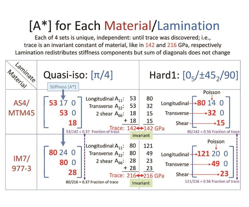
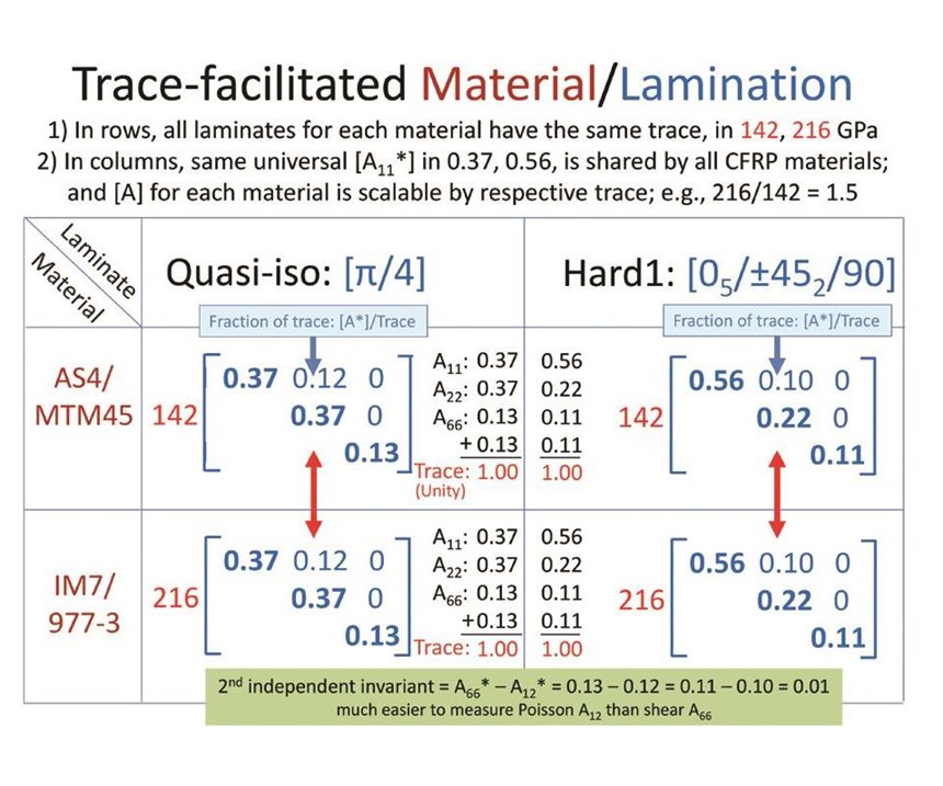
Trace is the sum of the three elastic constants of all materials — the longitudinal, transverse and shear moduli that are their diagonal components in the mathematical matrix of all carbon composites (see Fig. 1, at left). In the figure, two different carbon composite materials are shown, each in two different laminate configurations. But for both, if we add the diagonals (multiplying the third diagonal by 2) in each of the laminates, we get the same numbers for different laminates, for each material. This number is the trace of that material. In Fig. 2, we discover something more: We divide those same diagonal values by that material’s trace. What happens? In all four cases, we get 1.00. Regardless of the material or laminate, the result is 1. Each laminate, regardless of the material, has the same fraction of trace values, e.g., 0.37 for the first laminate. In my work, this has proven true with all laminates for all carbon fiber-reinforced plastics (CFRP) materials. The implication is clear: Trace is a universal constant, and in CFRP, the fractions of longitudinal, transverse and shear moduli in trace are, likewise, constant. For example, the longitudinal stiffness is 88% of trace for all CFRP materials, and is so within 1.3% accuracy.
This accidental discovery has made composites much easier to understand, and for practicality’s sake, the use of trace can be made even easier by focusing primarily on the measured longitudinal stiffness, that is, trace divided by 0.88. Why? Because the transverse and shear, together, share only 12% of trace. They are small enough that they need not be measured for our purpose here. This makes sense because we all know that longitudinal stiffness is fiber-dominated, and the transverse and shear stiffness are matrix-dominated and, therefore, are not needed for the determination of laminate stiffness.
Trace, it turns out, is the only constant that clearly defines the stiffness of the material, and we’ve found it is the only constant that we need with CFRP. Thus, the design of CFRP composites can be as simple as that for metals because, as is true with the latter, we need to test for only one constant. (Trace, by the way, is equally applicable to glass-fiber and aramid-fiber reinforced polymers, but with less accuracy than with carbon; i.e., with variation greater than 1.3%.)
Why not just use the longitudinal stiffness, and forget about trace? There is a fundamental difference between the two. Trace is an invariant. It does not change when the coordinate system rotates. Longitudinal stiffness, on the other hand, changes as we rotate it. It does not stay constant like trace. Trace is analogous to the weight of a laminate. It weighs the same regardless of how we rotate it.
How does trace help? Let’s imagine, for example, that a change or changes have been made to your CFRP material for a molded part. That you will have to run tests to determine what effects those changes might have on its properties is a given. If the trace of the CFRP material doesn’t change, you immediately know you’re on safe ground. Your properties are unchanged. But what if the trace of the CFRP material with the altered resin is, for example, 10% greater than the trace of a CFRP sample made with the legacy resin? Then you know immediately that the new version will be 10% lower in deformation, 10% higher in buckling, and the square root of 10% higher in natural frequency for all laminates. That is how powerful trace is. No other constants can deliver this kind of reliable aid. We need only one test to determine the value of trace (Ex/0.88 for the CFRP material). With that trace value, you can, in fact, derive all the constants of all laminates.
Trace also can make the coefficients of governing equations for not only deformation, buckling and natural frequency, but also vibration and stress concentrations, such as open- and filled-hole, universal as well. And we can turn this around: Each laminate only needs to be solved once, and the same solution is applicable to all CFRP materials. The buckling loads, for example, for AS4/MTM45 and IM7/977-3 (in Figs. 1 & 2) differs only by their relative trace values; i.e., the factor is 1.5. The same ratio would be valid for deformation and deflection. For natural frequencies, it would be the square root of 1.5, or 1.22. For stress concentration of an open-hole tension (OHT) or compression (OHC), the factor for [π/4] is 3 for all materials. (For a different laminate, such as [0°5 /±45°2 /90°], this factor will be different, in this case, 3.25.) There are supporting data to show that OHT and OHC are more dependent on laminates than materials.
The implications of these universal connections are far-reaching. One of the most important is that for testing. We no longer have to start from scratch with each new material and conduct thousands of hours of coupon tests to establish design allowables. If we have already tested and established the design allowables for one CFRP material, we can, in fact, derive the allowables data for all other CFRP materials, using simple mathematical calculations based on the ratio between the traces of the materials. Our physical testing, then, could be limited to the much less time- and cost-intensive series required for validation of the manufacturing process of the panels and their coupons, and the care in testing and data analysis. Trace sets the standard. We engineers just have to see how well we can do to match the prediction in the fabrication process.
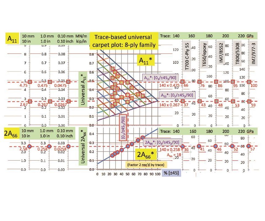
This has an impact on design charts, such as the carpet plots developed by the early pioneers in the 1960s. These have had limited utility in the composites industry. The reason why is that the laminates shown in a carpet plot, such as [0°5 /±45°2 /90°] and [0°/±45°/90°], are discrete; that is, there is no discernable thread or connection between any two laminates. But trace could change that. In the sample carpet plot (Fig. 3), with the percentage of (±45°) plotted on the horizontal axis and the fractional stiffness on the vertical axis, five materials are indicated, with their traces listed on the top line. You get all you need in the laminate stiffness. For each material, the difference is merely in the ratio of their traces. That makes the carpet plot for every laminate universal: We can make one carpet plot for all CFRP materials, not one for each material Trace is not a passing fad. It shows us that laminates and CFRP materials are interrelated, mathematically, and therefore, those who understand and accept those relationships and learn to use them to their advantage can make part design, development and manufacture easier and faster and, therefore, less expensive and more profitable.
Beyond that, however, I also contend that with trace, better laminates can be selected, leading not only to parts with less weight and greater strength and toughness, but less challenging stacking sequences. Today’s sometimes “bricky” and “patchy” designs with 8- or 10-ply families (with dozens of members) could become a thing of the past, traded in for more homogenous laminate designs that feature thin sub-laminates of a few plies. Trace offers the opportunity to vastly simplify simulation with homogenized laminates instead of the highly heterogeneous designs.
Suffice it to say at this point, trace is the quarterback or star pitcher of a new team. It is that important. It opens a totally new vista in composite design, testing and manufacturing. Don’t leave home without it.
Related Content
Automotive chassis components lighten up with composites
Composite and hybrid components reduce mass, increase functionality on electric and conventional passenger vehicles.
Read MoreMcLaren celebrates 10 years of the McLaren P1 hybrid hypercar
Lightweight carbon fiber construction, Formula 1-inspired aerodynamics and high-performance hybrid powertrain technologies hallmark this hybrid vehicle, serve as a springboard for new race cars.
Read MorePlant tour: Joby Aviation, Marina, Calif., U.S.
As the advanced air mobility market begins to take shape, market leader Joby Aviation works to industrialize composites manufacturing for its first-generation, composites-intensive, all-electric air taxi.
Read MoreTPI manufactures all-composite Kenworth SuperTruck 2 cab
Class 8 diesel truck, now with a 20% lighter cab, achieves 136% freight efficiency improvement.
Read MoreRead Next
Overnight design allowables? An invariant-based method for accelerating aerospace certification testing
Dr. Stephen Tsai, professor research emeritus in the Department of Aeronautics & Astronautics at Stanford University, suggests a way to accelerate certification testing via “overnight design allowables.”
Read MoreCompoSIDE and Trace: Game-changer for development of composite parts
Structural design challenges (delamination, coupling and shape distortions, resin-driven failures, local stress concentration and the like) are inherent in laminate architecture. The author's contention is that a solution can be found in design simplification afforded by the work of Dr. Stephen Tsai in Trace-based analysis.
Read MoreDeveloping bonded composite repair for ships, offshore units
Bureau Veritas and industry partners issue guidelines and pave the way for certification via StrengthBond Offshore project.
Read More


.jpg;maxWidth=300;quality=90)


